
Different programs implement propagation delay removal differently. Several have a function to directly align the impulse’ peak to 0ms, but others may require a manual placement of the cursor/marker. The placement of the cursor/marker can indicate a left rectangular window or a cut off.
One thing to remember is that the impulse response of the loudspeaker starts when the direct sound arrives to the microphone. It is important to understand that the peak of the impulse response does not always correspond to the initial energy arrival. Using the peak of the impulse response as reference point may result in a misleading or not meaningful phase response calculation.
Minimum Phase at Glance
Minimum phase is a condition where magnitude and phase responses have a predictable relationship. A change in magnitude response is followed by a change in phase response, corresponding to the Hilbert transform calculation. Most loudspeaker systems are not minimum phase system, but most transducers are. Another example of a minimum phase system are the infinite impulse response (IIR) filters with the exception of the all-pass filters.
The visual minimum phase relationship between magnitude and phase responses can be seen in figure 14.
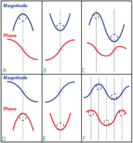
Figure 14
A positive value in phase shows a condition where the phase leads at that frequency. In a minimum phase system, phase can have positive values if the frequency response is rising up (from low to high frequency) such as a high pass condition, which usually occurs at the lower frequency response of a transducer. Another important point is a low pass condition where the frequency response is rising down. In a minimum phase system, this will result in minus phase values (lagging).
Let us observe a modeled one-way loudspeaker response with IIR filters, a high pass at 60Hz and a low pass at 12500Hz in figure 15 below.
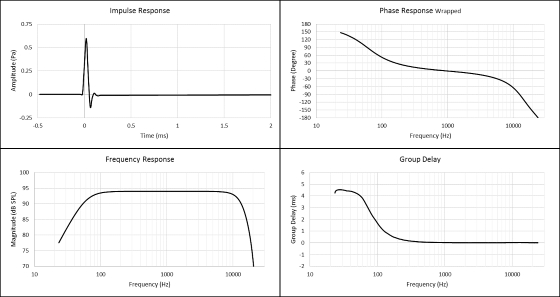
Figure 15