Propagation Delay and Phase Response
Why do we need to worry about the starting point of the impulse? Let us examine the effect of propagation delay on a phase response.
Propagation delay can result from different things such as:
—Time of flight
This is the time required for the direct sound to arrive to the microphone. Sound travels in the air at approx. 344 m/s (@20°C). It is important to know that sound requires time to travel in the air.
—Processor’s latency
Digital processing or digital to analog or analog to digital conversions often requires processing time. A typical latency for a digital loudspeaker management system from A/D to D/A conversion is approx. 2ms. With heavy processing, a digital processor can require longer processing time, resulting in additional propagation delay.
—FIR (finite impulse response) filters
Using FIR linear phase filters may result in additional propagation delay. The filter’s processing delay can take as small as 1ms up to >500ms depending on the applications.
In figure 4 below, let’s assume a ‘perfect’ loudspeaker is measured using a dual-FFT and the blue colored impulse is obtained. A 0.5ms propagation delay is observed (the ‘perfect’ microphone is assumed at approx. 17cm away). The black colored impulse shows that propagation delay is removed correctly so the peak of the impulse is at 0ms.
This is done by cyclic shifting of the impulse response (this will be explained below). The red colored impulse shows the location if the propagation delay is removed 0.5ms too much. The red colored impulse is an acausal response where the output is not caused by the input. An impulse before 0ms can also be thought that the output happens before the input is fed to the device.
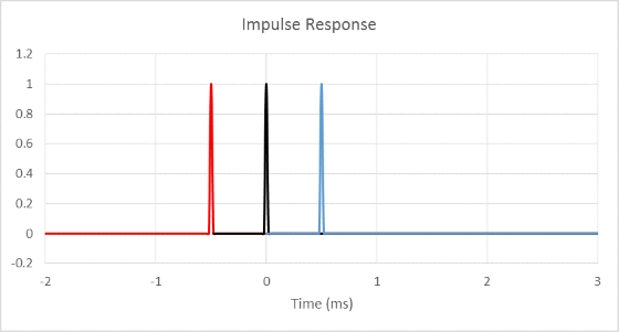
Figure 4
Figure 5 shows the phase response when the propagation delay is removed correctly, where the peak of the impulse is at 0ms. Please observe that the phase response is flat at 0deg and group delay is also at 0deg.
Group delay is the negative rate of change of phase with respect to frequency. The group delay equation can be seen below:
τ_g (Ω)=-dφ/dΩ; Where:
Ω (omega) is angular frequency or 2π times frequency.
φ (phi) is phase.
τ (tau) is group delay.
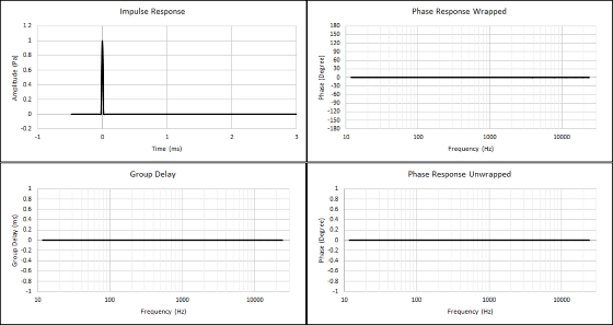
Figure 5
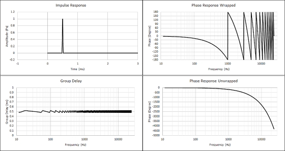
Figure 6
Moving on to figure 6, please observe the phase response when the 0.5ms propagation delay is not removed. To see the phase response clearly, figure 7 shows the zoomed version of the unwrapped phase response.
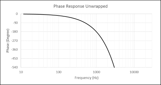
Figure 7