
This is an ongoing series guiding architects, and others, through the world of acoustics. In Parts I , II & III (Part 1, Part 2, Part 3) we’ve defined architectural acoustics; explained what sound is; highlighted the three main types of sound propagation; offered a baseline acoustics lexicon; described echo, reverberation and resonance in some detail; elaborated on the three acoustical tools; and answered the question: Where does all the unused sound go?
This installment introduces two more foundational branches: Section 8 examines Room Geometry. Section 9 looks at issues related to Acoustic Shadowing.
This commentary is based on fundamentals and the author’s experience – not perfection. It covers many of the basics, while also exploring several modern and esoteric matters. You’ll be introduced to interesting and analytical subjects; some you may know, some you may never have considered.
If you’ve just joined us you might wonder: Why offer this material to the pro-audio community when the target audience is architects? The simple answers: Most pro audio practitioners have to work in acoustic environments that are out of their control because of past decisions made by an architect or owner. When complete, my goal is to transform this lengthy commentary into a book that architects can easily access. Also consider that there are probably many new and veteran sound techs that have yet to accumulate a solid acoustical foundation. Most certainly, there are knowledge gaps on both sides of the designer/user relationship.
Hopefully this information will be of interest to many, and that you’ll find value that can be shared with others, including the owners and architects you may interact with on a regular basis.
This commentary is being serialized over the course of many episodes. If you haven’t already, it’s a good idea to start from the beginning as each new installment builds on its predecessors. For example: The Section, reference, figure numbers, and acronyms sited in each publication continue from the previous issues.
8.0 ROOM GEOMETRY – THE GOOD, BAD AND UGLY
8.1 Architectural geometry and architectural acoustics are inextricably linked. Most rooms – having complex interior geometry – will complement and support good sound better than ones with simple geometry. This Section attempts to explain why room geometry has such a significant impact on sound and acoustics.
8.2 Room geometry all boils down to issues related to flutter echo (see Part II, Section 5.3.2) and room modes (see Part II, Section 5.5). Given enough volume and reflective surface area, reverberation can and will exist in all rooms, regardless of shape.
A. The ubiquitous six-sided, rectangular “shoebox” room is a very common architectural shape. Each opposing pair of surfaces is parallel. All corners are set at 90 degree angles. A very simple three dimensional shape, and typically, very cost-effective to build.
B. When more complex interior geometry is suggested, we’re talking about rooms with more than six major walls; convex curves; obtuse angles; tilted or rotated walls; alcoves; balconies; ceilings that are not parallel to the floor; and sloped or stepped floors, etc.
C. In addition to the basic geometrical decisions, other important factors to consider are elements such as the physical placement of the sound source(s) in relation to the listeners; a room’s interior dimensions; the inclusion and use of a sound reinforcement system; and the LF/VLF content to be presented.
-
- Are you being asked to design a 30’ x 30’ classroom, a huddle space, a worship center, a multipurpose building, a sports arena, or a performing arts venue? Acoustically, each has a unique set of challenges.
D. Let’s now consider various room shapes and volumetric ratios. The following list includes many possibilities. Acoustically, not all are particularly usable, but they do illustrate key concepts relating to the ideas being expressed throughout this commentary.
-
- Following the listing of common geometries that begins with Spherical Rooms, an overview of common ceiling topologies is outlined in Section 8.17 below.
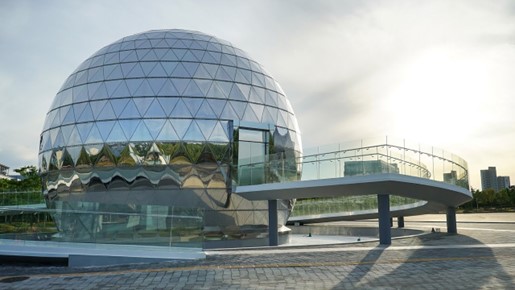
8.3 Spherical Rooms
A. The inside of a sphere (Figure 45) is generally the worst acoustical shape. Because this isn’t a practical building shape for most public venues, it’s rarely seen, and not worth much further commentary other than these few points: The problems with spherical, or near-spherical rooms are primarily modal and focused, specular reflections.
-
- Spheres simply don’t provide enough modal density and variety. There’s only one interior dimension; the diameter of the sphere. A perfect sphere produces only one, dominant, resonant frequency, which is based on the diameter of the space.
- Much like concave walls and domes – which are covered in more detail below – the untreated, interior surface of a sphere causes reflected energy to be concentrated in a very specific area of the room. The location is at, and near the focal point of the spherical radius.
a. For near-spherical rooms, there can be multiple focal points. The size of the room, and the arc radius of the various curves, determine their location.
b. This concentration of sound energy is often much louder than the nominal sound levels in other parts of the venue, and may also include audible, flutter echoes.
B. There is also the phenomenon of “whispering galleries” to consider. This is the experience that occurs when you whisper near the wall and some other person, far away, hears you loud and clear.
C. If you are planning for a spherical room that will be used for public assembly, one of your first phone calls needs to be to an acoustical consultant. There will be much work, and expense, required to make this shape sonically tolerable.
D. Conversely, the outside of a sphere is an excellent shape when located inside of almost any room. Regardless of size, it becomes a very effective, convex scattering element.
8.4 Cube Rooms
A. Cubes are the worst of the realistically-usable room shapes. The problem is all three major dimensions are equal, and each of the three pairs of surfaces are parallel. This configuration results in a bad set of room ratios, which are the ratios of length to width; length to height; and width to height. In short, due to a lack of dimensional variety, there’s not enough modal density and variety. See more on room ratios in Section 8.14 below.
B. Cubical rooms have fewer and stronger modal peaks and valleys than rooms with optimal aspect ratios.
C. Also, if not carefully treated on at least three, non-opposing faces, problematic flutter echo will potentially dominate the listening experience.
D. Some careful planning, and a reasonable treatment budget will be required to make a cubic room sonically viable.
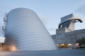
8.5 Round/Cylindrical Rooms
A. Round rooms – with or without a parallel floor and ceiling – are a difficult shape for any sound-related activity. (Figure 46)
B. Acoustically, round rooms behave much like spheres. Without significant amounts of absorptive and/or diffusive materials being incorporated into the curved walls, this footprint will likely be challenging for public assembly of any size. Ovular and egg-shaped rooms have similar problems.
C. The primary issue with round, cylindrical, and oval rooms is the focusing of excess sound energy toward a fairly small area, at and around the center of the arc radius. You should be starting to notice a theme: Regardless of size, concave boundaries are not acoustically friendly for most rooms used for public assembly, and/or audio presentations of any kind.
D. If you must design a round room, moving to a cone shape (Figure 47) will help, providing the tilt gradient is at least 1:12, and the floor and ceiling are not parallel.
8.6 Rectangular Rooms
A. Rectangle plans are probably the most common shape for commercial venues. The geometry is simple and obvious. Picture the common shoebox. Once the decision has been made to build a rectangular room, the subject of room ratios should become a priority. It’s prudent to evaluate, and potentially adjust the ratios if the space will be used to generate or receive any meaningful audio content; be it spoken word or music.
B. The length, width, and height dimensions should all be different, and not an exact multiple of each other. Example: A rectangular room that’s 12’ high, 24’ wide, and 36’ or 48’ long would not be a good place to start.
-
- Direct multiples are problematic because they lack dimensional variety. A poor distribution of room modes will occur. And, because of this, significantly large gaps will occur between the few modes that develop. The result is that the most prominent modal resonances can be easily heard by most people. Low frequency room modes should be spread out as evenly as possible.
- In case this wasn’t made clear earlier, the goal is not to eliminate all modal activity. What’s desired is a significantly large number of closely-, and evenly-spaced modal resonances – at and below Fs.
C. Contrary to common belief, flat, parallel walls are not automatically a negative acoustical factor. However, there are potential acoustic problems if the room is not designed with some care beyond the basic construction requirements.
-
- 19th century European concert halls all have parallel side walls. They provide psychoacoustic widening of the natural sources from stage end, and their ornate decorations provide some useful scattering.
- Bare walls will very likely need some form of acoustical treatment on at least two, non-opposing walls. If left untreated, flat, reflective, parallel walls create an environment that generates and supports flutter echo.
- If the floor and ceiling are parallel, some form of acoustical treatment will likely be needed on at least one of those surfaces too. In small and medium-size rooms this is often carpet and/or acoustical ceiling tiles. However, because it’s so thin, carpet is one of the least effective VB (velocity based) absorbers.
8.7 Triangular Rooms
A. A triangle is not a common building shape, but it does present one nice feature; the side walls are about as far from parallel as possible. Flutter echo shouldn’t be a problem, unless it occurs between the floor and ceiling.
B. To address appropriate room ratios, try to avoid equilateral triangle plans.
8.8 Quarter- and Half-round Rooms
A. In recent years these shapes have become popular for performing arts and house of worship venues. While these shapes can be quite good when considering sightlines, and a need to bring the audience as close to the stage as possible, they too can present acoustical challenges.
-
- One example is that the side walls will not provide any useful, early reflections. Side wall early reflections are an important feature in rooms that are designed specifically for unamplified speech or acoustic music. Once a sound reinforcement system is employed, the need for early side wall reflections often becomes moot.
B. Any concaved, interior wall surface presents an acoustical paradox.
-
- If the concave surface is located at or near the rear wall of a stage or platform, it may serve as an effective and perhaps even desirable acoustical reflector, which may enhance certain styles of unamplified speech or musical performance. In theatrical terms, the part of a stage closest to the rear wall of the stage is called, “upstage.”
- If the rear wall of the “house” (opposite the stage) has a concave shape (Figure 48), it will be acoustically problematic, and will very likely need some specific treatment (Figure 49) in order to minimize the negative effects (arc radii focusing) of the reflected energy bounding off the curved surface.
- Regardless of whether the back wall is a true curve, or a facetted curve, the detrimental effects are very similar.
8.9 Trapezoidal Rooms
A. Like the quarter-round shape, the trapezoid room (Figure 50) has one notable advantage: at least one set of walls is not parallel. This shape helps break up side-to-side flutter echoes, and creates more complex modal behavior in the LF and VLF regions.
-
- The severity of the side wall angles determine how much of the center seating is removed from useful side wall reflections, and pushed toward the edges.
B. The greatest disadvantage of the trapezoid shape is that the front and back walls are often parallel. This configuration will require further evaluation and treatment if not properly factored into the initial design. Here are some solutions to consider:
-
- Tilt one or both parallel walls, using the minimum 1:12 slope gradient offset.
- Add convexities, as shown in Figure 49, to one or both walls.
- Add perf or slat absorption panels to cover at least 50% of one of the surfaces; preferably the curved back wall, opposite the sage.
- Include non-parallel slope to the floor and/or ceiling.
- If needed, mix in some PB (pressure based) absorption devices along with the VB treatments.
8.10 Pentagonal Rooms
A. The pentagon (Figure 51) is my favorite flat-wall shape because it offers a large seating area, good sight lines, and no major parallel or concave walls.
B. As nice as this shape may appear on first glance, there are still potential acoustic issues to be considered for this, or any other room shape. These are based on:
-
- The dimensions of the wall segments, which translates into finding the optimal combination of room ratios. (Figure 52)
- The height and slope angle(s) of the ceiling.
- The slope angle of the floor.
- The location of various key elements such as a stage.
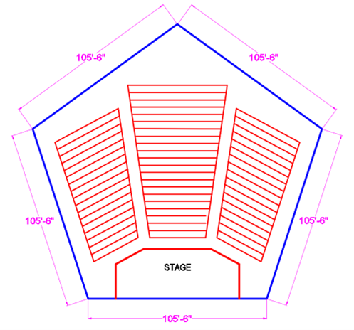
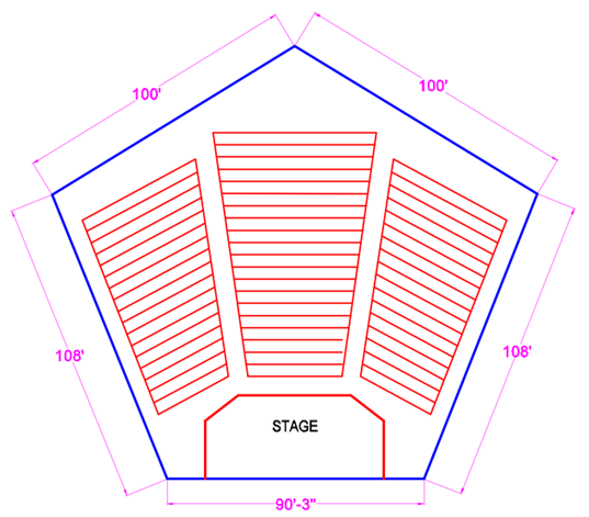
C. Presuming a ceiling height of 30’, and that the floor and ceiling are parallel; the room ratio for Figure 51 is 1.0:3.52. Because all five sides are equal length, this is not and optimal layout.
-
- After minor dimensional adjustments, the ratios shown in Figure 52 become more advantageous – 1.0:3.01:3.33:3.60.
- To further improve the pentagon, vary the length of each wall segment so no two are equal, and vary the slope of the floor and ceiling so they are not parallel.
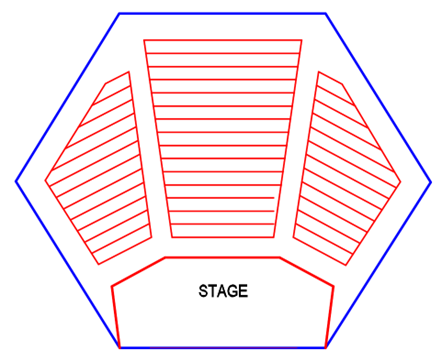
8.11 Hexagonal Rooms
A. Adding more wall facets is not necessarily better. The hexagon plan (Figure 53) falls back into the shortcomings of the rectangular group because it has multiple parallel walls. All the same precautions must be taken related to flutter echoes, room modes, and room ratios.
8.12 Heptagonal and Octagon Rooms
A. Much like the pentagon, heptagons (seven sides) are a potentially good shape to consider. However, now construction costs start to climb, but with little or no acoustical benefit.
B. Octagonal (eight sides) plans have the same issues as hexagon and heptagon plans.
C. In both cases, as the number of facets increase beyond six, rooms become closer and closer to being round, which is not a desirable acoustical goal.
8.13 Concave and Convex Surfaces
A. There is no question that architectural structures take on many other more complex shapes than those outlined above. Acoustically, all solid architectural finishes constitute either flat or curved surfaces. Flat surfaces have been addressed above. Let’s now look at the merits of these two, curved-surface shapes.
B. Concave: All concave surfaces– such as shown in Figure 48 – are acoustically challenging if finished with hard, reflective materials such as sheetrock, concrete, wood, glass, etc.
-
- As noted earlier, concave surfaces concentrate reflected sound energy into a small area. The density of concentration, and the size of the focal area, are largely determined by the arc radius of the surface; the distance between the focal point and the listener(s); and the overall size of the curved surface.
- Focusing reflected sound is usually not desirable, and should be avoided in most situations. Yes, there are exceptions to this guideline, but they are few.
C. Convex planes: All convex planes bring the exact opposite results, and are generally encouraged, where and whenever possible.
-
- Convex planes are inherently diffusive, which is good. More often than not, convex planes result in improved acoustics and sound management.
- Faceted convex planes are less complementary, but still beneficial. The number of facets, and the arc radius of the overall curvature, will determine the relative benefits. More facets generally bring better, more even results.
- If a building’s design is able to include two or more, mirror-image, convex planes, regardless of location, the need for additional diffusive or absorptive materials may be reduced.
8.14 Room Ratios
A. Dimensionally, rectangular rooms are commonly described as having a given height, width, and depth (hwd). However, the nouns length, width, and height (lwh) are also commonly used, and can be considered equal and synonymous.
B. In rectangular rooms, the ratios start with the smallest of the three dimensions representing a factor of 1.0. In the 12’x24’x48’ example noted above, 12’ equals 1.0. From there each of the other dims is compared to provide its ratio – relative to 1.0. Therefore, the room ratios for this example are 1.0, 2.0, and 4.0 which are commonly presented in ratio sets like this: 1.0:2.0:4.0.
C. In recent research on room ratios in small rectangular rooms, it has been found that, “the length-width ratio is much more important than the width-height ratio. The length-width ratio should be within 1.15–1.45. The height can be chosen more freely without compromising the acoustical quality.” [33]
D. For rooms larger than about 11,000 ft3, there are many “optimum” ratio sets stated in the technical references. Here is one example: 1.0:1.4:1.9.
-
- A roughly 9,000 ft3 room might have a 15’ ceiling, and be 21’ wide and 28.5’ deep. This would be a very nice rectangular room shape to work with. Need a bigger room? Double all these dims so the room becomes 42’ x 57′, with a 30′ ceiling. The ratio set stays the same.
- Many other good-to-optimum ratios exist, so you’ll have several options to consider. Your friendly, local acoustician can help you find the best ratio set for your project.
- If the room you’re planning will be something other than a rectangle the ratios are somewhat less critical because you are potentially introducing much more modal variety. Having lots of modal variety is a good thing.
- Designing around one of the optimum ratios is not the only factor to consider, but it’s a good place to start if you’re designing a rectangular room that will be used for some type of sound generation or reception.
8.15 Symmetry
A. If the purpose of a room is to support live performances or the presentation of other meaningful, audible information, it’s tremendously helpful to design a symmetrical interior shell and seating layout. To be clear: symmetry does not imply simplicity. To recap: complex geometry is usually a beneficial acoustical feature.
B. One of the prime goals and challenges for sound system designers is to deliver even sound coverage to all seating areas. Architects can help with this. There are significant performance, cost, and aesthetic benefits achieved when a room is designed with mirror-image symmetry along the center line axis of the stage or platform. It’s important to note these points:
-
- Good quality sound reinforcement requires careful time domain implementation. A sound system that is not properly “time-aligned” is analogous to a photograph that is out of focus.
- One critical architectural deliverable is providing the best possible sightlines. Delivering good-to-excellent amplified sound propagation is analogous to supplying good-to-excellent sightlines.
- If one of the design directives is to have multiple, terraced, floor elevations on the main floor, try to limit the variations to be no greater than +/- 2’.
- Every major building element or feature, which introduces significant asymmetry, obstructions, or other irregularities to the floor plan, ceiling, and/or audience seating area(s), may result in an inconsistent acoustic environment.
a. Additional sound devices, labor, structural points, and aesthetic anomalies can all become unexpected challenges brought on by the need to support an asymmetrical seating and/or building structure. Obviously, each of these adds cost and technical complexity to any project.
-
- There are some exceptions; times when specifying “zoned acoustics” is an appropriate and desirable goal. Application-specific, acoustic zones need to be carefully planned, and purpose-built.
8.16 Flex Spaces
A. Occasionally multipurpose rooms are used with various seating configurations; where the “front” or focal point of the room may be located just about anywhere. These are sometimes called flex spaces.
-
- The Perelman Performing Arts Center in New York City is a good example. According to Rob Miller at Threshold Acoustics, “the acoustic challenges were resolved with largely diffusive surfaces.”
B. In rooms with fairly simple geometry, the acoustics, be they good, fair, or bad, will not change because of the orientation of the seating layout. However, flex rooms do present additional sound, video and lighting system costs, and operational complexities.
8.17 Ceiling Layouts
A. Ceiling layouts are another important element within the acoustical environment. Ceiling symmetry is just as important as floor plan and wall symmetry.
B. If a room is to have a single, interior ceiling slope, it’s helpful to have the highest point in the room located above the stage or platform, with the ceiling gradient sloping downward as it moves toward the back wall of the room.
-
- The slope gradients should be in the range of 1:12 to 3:12. Anything that’s less than 1:12 is acoustically insignificant, and may as well be flat. A gradient that’s greater than about 3:12 has its challenges too
- If there is a sloped or stepped floor planned, slant the floor and ceiling in opposite directions, so the angle opens widest at, or near, the front edge of the stage. In theatrical terms, this is called, “downstage.”
- Gradual, yet acoustically-significant slope changes are much preferred over dramatic changes.
a. One challenging example can be seen in buildings that have a central clerestory, with a significantly lower ceiling structure beyond. See more on this in Section 8.18 below.
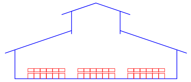
C. The A-framed Roof Structure
-
- If a room design calls for an A-frame ridgeline it is best if the ridge beam runs parallel with the center line of the stage or platform; not perpendicular.
a. Several presentation and propagation challenges are created when the ridgeline is turned sideways so it’s parallel with the front edge of the stage. This configuration tends to encroach on appropriate loudspeaker placement, and the size and location of video screens or displays.
b. Also, it’s best when the overall slope gradient, on either side of the ridgeline, is “flattened” so the lowest point of the slope – at the outer walls – is equal to or higher than about 50% of the peak ceiling height. Read a slope gradient of 6:12 or less. Example: A room with a 30’ ridgeline should have walls that terminate at 15’ or more in height.
c. For ceilings that slope continuously from one side to the other, the 6:12 recommendation applies too, though a 2:, 3:, or 4:12 gradient would be even better.
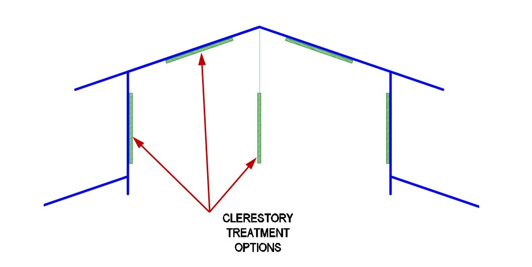
8.18 Clerestory Roof Structures
A. In rooms that have a fairly uniform shape and ceiling height, reverberation will behave and sound the same in every seat. In rooms with clerestory roof structures, reverberation increases directly below. (Figure 54)
B. Because reverberation time is directly related to room volume, the sudden expansion in volume under the clerestory creates reverberation times that are somewhat longer than those measured in seating areas on either side. The length, width, and height of the clerestory control the variation.
C. To help normalize the reverberation under a clerestory, a good solution is to add VB absorption treatment where possible. Figure 55 shows three different options.
8.19 Domes
A. Domes may look creative and artistic, or convey a desired sense of grandeur, but they will almost always result in a room that doesn’t work well for good sound creation or propagation. Domes have many of the same issues as spherical, cylindrical, and round rooms.
-
- Picture a room or venue with a large domed roof, or even a smaller area with a domed ceiling that covers sound sources (voices and/or instruments), and/or an audience of some sort. Again, without the addition of custom acoustic treatments – many of which may be generally unfeasible, aesthetically unacceptable, and very expensive to implement – domed ceilings should be avoided.
B. If you must deliver a dome ceiling of any significant size or location, be sure and include an acoustical consultant on your engineering team. Also include a budgetary line item for some “creative”, and often expensive, acoustical treatment within and/or below the envelope of the dome.
-
- Though not a total solution, the floor area directly below a dome must have a soft, VB-type absorptive finish. The combination of carpet and soft padded chairs/pews is a good option.
8.20 Elevations
A. Last, but far from least important are the room’s overall interior elevations.
B. If only one architectural wish could to be granted, I would opt for more usable ceiling height. Here, the term “usable” means unobstructed. No other single, structural parameter makes the presentation of good sound, video and lighting more difficult, and expensive, than the lack of adequate vertical space; especially above and around a platform or stage.
C. The larger the room, the more ceiling height that’s needed.
-
- If good results are desired and/or expected, a 20′ ceiling should be considered a minimum guideline for a 5,000 ft2 room that’s being designed for presentation or performance.
- At 10,000 square feet, the usable ceiling should be at least 25′ at the lowest point.
- Yes, of course there are exceptions. Exceptions become workable solutions when careful, creative planning, and a little greater expense are allowed to coexist.
8.21 Low Ceilings and Soffits
A. Alone, low ceilings don’t render poor acoustics. However, the lower the ceiling, the greater the restrictions and limitation become for good sound propagation from a loudspeaker system.
B. Try to avoid adding any type of soffit that runs directly above the stage, and/or primary seating area(s). Even a small soffit, running above any key areas, can effectively define the lowest point for the entire room or platform.
-
- A mid-room soffit can easily translate into more complex and expensive audio, video, and lighting (AVL) systems.
a. Example: If a room has a general ceiling height of 28′, but has a soffit running through the middle of the room that finishes at 24′ AFF (above the finished floor), effectively – for some or all AVL propagation purposes – the room has a ceiling height of 24′.
b. Without adding additional speakers, middle and high frequencies may be blocked, and not able to reach very far beyond the soffit; loudspeakers may need to be mounted too low; camera angles and video projection cones may be clipped; and theatrical lighting may have to be mounted too low, restricting good lighting angles.
c. The mid-room soffit scenario doesn’t necessarily impact the room acoustics as much as it impacts unobstructed AVL propagation.
-
- If soffits can be pushed out to the far side or rear edges of a room, this concern is significantly minimized.
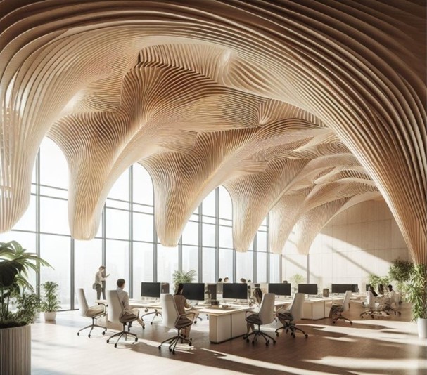
8.22 As this commentary is being written the implementation of AI seems to be pervasive. Pascal Van Dort, Global Acoustics Ambassador at Rockfon, recently posted this graphic (Figure 57) on LinkedIn. He asked his AI app to create an image of an open-plan office, with excellent room acoustics, in the style of ten internationally-known architects. This is my favorite of the ten. The other nine can be see here [34]. The human imagination should be no less wondrous.
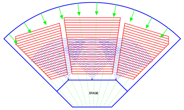
9.0 ACOUSTIC SHADOWING
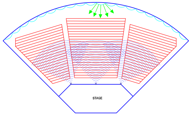
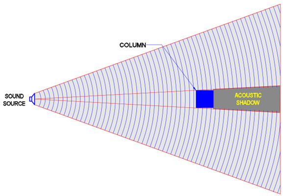
9.1 Acoustic shadowing occurs when objects block the direct flightpath of sound energy between a sound source, and one or more listeners. This subject comes into play more often than might be imagined. The most common examples are seen in large assembly areas that have columns, balconies, truss beams, and/or large lighting pendants.
9.2 This scenario is easily demonstrated and understood by using this simple test: If a listener cannot see all of the nearest loudspeaker, or other sound source they are expecting to clearly hear, some or all the MF and HF content will be obstructed – creating an acoustic shadow. This matters a lot if you’re client is concerned about speech intelligibility, because the primary frequencies needed to deliver good speech clarity and intelligibility fall between 500 Hz and 4 kHz. Most of those frequencies are easily shadowed or blocked.
9.3 The trig calculations needed to quantify the problem are too complex for this commentary, therefore let’s stick with these basic concepts:
A. The largest dimension of an obstruction is not necessarily the most “significant” dimension. The most significant dimension is usually the one obstructing sound from getting to one or more listeners – on the horizontal plane. (Figure 58)
-
- Example: For any given seat, the significant dimension of a 12″ square column, which is 15′ tall, is almost alwalys12″, not 15′.
B. Acoustic shadowing can be parsed into three ranges: Full blockage, partial blockage and no blockage.
-
- Full blockage: If the most significant dimension of the blocking structure is equal to, or greater than, two times the wavelength dimension of concern, most or all sound at that frequency – and above – will be blocked.
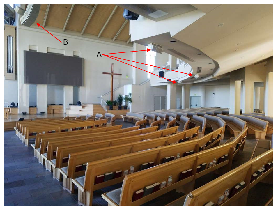
a. An obvious example of this occurs when a balcony overhang blocks the direct flight of sound from a sound system. (Figure 59)
-
- Partial blockage (technically known as the “diffraction zone”): When the most significant dimension is between one-quarter and two times the wavelength dimension of concern, those frequencies will be partially blocked or diffracted.
a. The diffraction zone includes those wavelengths that are able to partially wrap around the obstruction in question, but without full power and fidelity. These frequencies may be audible, but will be distorted – in time and energy – relative to the direct, unblocked sound arriving in the same general area.
b. Example: Let’s take a single frequency such as 1,500 Hz, which is near the middle of the four octaves of sound that are most important for speech clarity and intelligibility. The wavelength of 1,500 Hz is 9”. The quarter wavelength is 2.25″. Therefore, based on these dimensions, any obstruction larger than 18” will fully block sound that includes content at 1,500 Hz and higher. Partial blockage will also begin at that frequency if the obstruction is as small as 2.25”.
-
- No blockage: When the most significant dimension of an impediment is smaller than one-quarter the size of the wavelength dimensions in question, no significant blockage occurs.
C. The grand takeaway: There should never be an object that blocks the line of sight between any listener position and the sound source or loudspeaker that is providing direct coverage to those positions. If you want to take a deeper dive into this subject, see this article: Acoustic Shadowing: Unpacking Wave Numbers (k) & Introducing the Wave Ratio Thesis. [35]
9.4 I’m reminded that at some venues “obstructed seating” tickets are sold. What’s implied is a visual obstruction to what’s presented on stage. It’s never an audible obstruction. Nevertheless, if you can’t clearly see (presuming sufficient lighting) the front of the speaker(s) that’s supposed to be covering your seat – because of some structural obstacle – you too will have an obstructed seat. Need I say more?
Final Thoughts:
That’s it for now. Hopefully, you’ve learned a few things you didn’t already know, and are looking forward to what comes in the next installment. There we’ll delve a little deeper into speech intelligibility; outline three simple, non-technical acoustical tests; lay out the differences between internal and external noise; characterize the various means and methods of variable acoustics; and take a peek into psychoacoustics.
One of the essential goals of this commentary is to encourage architects to put as much time, effort, care, and awareness into optimizing the acoustics in their room designs as they put into satisfying the customer’s needs for lighting, heating, and air conditioning.
If you remember nothing else from this series, please remain focused on this: For better or worse, every architectural shape, feature, location, and finish influences sound behavior and quality.
—————–
References:
[33] Preferred Dimension Ratios of Small Rectangular Rooms. Jens Holger Rindel Odeon A/S, DTU Science Park, DK-2800 Kongens Ly
—————————–
Peer Review Team
A special thank you goes out to Neil Shade, FASA (Acoustical Design Collaborative), Charlie Hughes (Biamp and Excelsior Audio Labs), and Rob Miller (Threshold Acoustics) for assisting with notes, comments, and corrections that made this work presentable.


