
This is an ongoing series guiding architects, and others, through the world of acoustics. In Part I and Part II we’ve defined architectural acoustics; explained what sound is; highlighted the three main types of sound propagation; offered a baseline acoustics lexicon; and described echo, reverberation and resonance in some detail.
This installment introduces two more foundational branches: Section 6 provides an overview of the Three Acoustical Tools that are commonly available. Section 7 answers the question, Where Does All the Unused Sound Go?
This commentary is based on fundamentals and the author’s experience – not perfection. It covers many of the basics, while also exploring several modern and esoteric matters. You’ll be introduced to interesting and analytical subjects; some you may know, some you may never have considered.
If you’ve just joined us you might wonder: Why offer this material to the pro-audio community when the target audience is architects? The simple answers: Most pro audio practitioners have to work in acoustic environments that are out of their control because of past decisions made by an architect or owner. When complete, my goal is to transform this lengthy commentary into a book that architects can easily access. Also consider that there are probably many new and veteran sound techs that have yet to accumulate a solid acoustical foundation.
Hopefully this information will be of interest to many, and that you’ll find value that can be shared with others, including the owners and architects you may interact with on a regular basis.
Because of its scope and length, this commentary is being serialized over the course of many episodes. It’s a good idea to start from the beginning as each new installment builds on its predecessors. For example: The Section, reference, figure numbers, and acronyms sited in each publication continue from the previous issues.
6.0 THE THREE ACOUSTICAL TOOLS
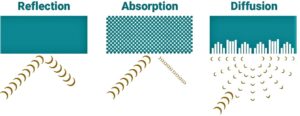
6.1 There are three primary acoustical “tools”, or methodologies, used to manage echo, reverberation, and resonance. Those tools are: reflection, absorption, and diffusion. (Figure 24) These are not actual tools, but rather they are adnouns that represent the acoustical properties and interactive behavior of various finish materials. These three words translate into product categories, materials, and application techniques that can be used to regulate how sound energy behaves in an enclosed space.
6.2 Reflection: With exceptions (Figure 25), reflective surfaces are typically not specified as mitigating acoustic treatments. Rather, they tend to support and sustain sound energy longer than may be necessary or desired. Yet they are very common finish materials that should be understood in the context of the overall room design.
A. Reflective surface materials are generally smooth and rigid. Concrete, tile, glass, wood, brick, metal, and sheetrock are common examples.
-
- If you shine a flashlight at a mirror you get a reflection, or bounce, which is nearly identical to the original light source. This is similar to what happens when sound bounces off smooth, flat, reflective surfaces.
B. When sound energy strikes a flat, reflective surface, the sound bounces off with nearly the same energy it had before striking the surface. These are sometimes described as “specular” reflections. (See “Echo” in Part II – Section 5.3.)
C. The application of reflective finishes range from good to bad, based on shape, size, and location. Acoustically, here’s how to prioritize specifying reflective finish materials.
-
- The good:
a. Almost anything that has a convex shape, regardless of size or location. Why? Because convex reflectors are essentially sound scattering devices, and sound scattering is almost always a good thing.
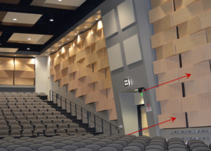
b. Any other complex geometry that redirects sound energy away from its source, and away from other parallel surfaces that are also reflective. This is the principle shown in Figure 25.
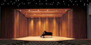
c. In venues built to host purely acoustic music, reflection is a tool of amplification that sustains sound energy, and promotes useful early reflections and reverberation. (Figure 26) Reflective surfaces support the weak sounds that are associated with choirs and acoustic instruments.
2. The acceptable, but potentially problematic if untreated:
a. Almost any hard surface that is flat and parallel with another flat, reflective surface of meaningful size, i.e. > about 10 ft2. These conditions promote flutter echo. (See Echo in Part II – Section 5.3)
i. To minimize flutter echo, reflective parallel surfaces can be partially or fully covered with absorptive and/or diffusive/scattering treatments.
b. Alternatively, those surfaces can be tilted, rotated, or staggered by at least a 1:12 offset. A 2:12 offset is preferred. Here, the treatment is not added products or materials, just simply the slight movement or repositioning of flat reflective structures.
i. For those who aren’t architects or general contractors, here’s what these ratios mean: For every 12” of linear distance, a 1” to 2” offset must be applied. In other words, a wall that’s twelve feet wide needs to tilt or stagger by one to two feet.
ii. When opposing walls are offset with mirror image symmetry, the offset effectively doubles the stagger, rotation, or tilt. More is usually better.
3. The bad:
a. Almost any concave, reflective shape. Depending on location and radius, reflective concave shapes can be extremely problematic. They collect and refocus sound energy; generally amplifying sound in unfavorable ways.
i. However, small concave surfaces – located high enough above the floor – will have focal points well above the listeners, and thereby provide useful scattering.
b. If not carefully located, analyzed, and treated, any form of curved/faceted wall – and/or arched or domed ceiling – is likely to introduce significant acoustical anomalies, such as:
i. For listeners, the refocused sound energy causes audible “hotspots”, depending on where one is seated under, or within, the focal radii of the curve, ellipse, or dome. And, depending on seating location, the refocused energy may also be heard as an audible slap echo.
ii. If any microphones are positioned within the focal radii, audio feedback squeals can easily become a common occurrence.
iii. Hard flooring and/or seats compound the problems because of the recirculating, specular reflections that occur.
D. To be fully effective at reflecting LF/VLF frequencies, finish materials must be very dense and rigidly mounted. Common construction methods are generally insufficient.
-
- Think about designs that use concrete or block walls, or require double or triple layers of sheetrock, with stud spacing no greater than 12 inches. There are only a few audio applications that require and benefit from such density. Symphonic concert halls that only present unamplified, acoustic music are one of the rare exceptions.
E. With all this said, hard reflective finishes are common, expected, and generally unavoidable. Therefore, the architect’s challenge is to develop designs that recognize the strengths and weaknesses of reflective finishes, and if necessary, acoustically treat them to optimize their performance within the overall desired or required acoustic signature of a venue.
F. Note: While acoustical scattering and diffusion are desirable outcomes, employing loudspeakers that randomly propagate scattered sound energy are not.
6.3 Absorption: Sound energy is absorbed when various materials and structures provide a means of converting its energy into heat. This happens when the energy strikes an absorptive or resonant wall, floor, ceiling, person, panel, boundary, or barrier of some type. The result is that some fraction or percentage of the sound – at each discrete frequency – will be converted to heat, thereby reducing its energy.
A. Before we dig in further, it’s helpful to briefly touch on the physics behind how absorption tools interact with sound. I realize these next several paragraphs may seem too deep for what’s supposed to be a non-technical commentary; bear with. The rationale is to also provide the “why”. Acoustics is already complicated and perplexing enough. Without touching on why sound energy is such a challenge to manage there’s little hope for advancing the subject into meaningful, proactive action in the dominions of architecture and ownership.
B. Due to the enormous range of frequencies, and corresponding wavelengths we can hear, sound energy is captured and dissipated in two distinctly different ways. One is “velocity-based” absorption, the other is “pressure-based” absorption. Because of this, two entirely different methodologies are required, depending on what range of frequencies need treatment.
-
- To avoid any confusion, we’re talking about absorption that’s attained as a result of slowing down the “particle velocity” – at the micro level – within the wave energy of an oscillation, not a change in the speed (velocity) of sound.
C. It’s all about the Schroeder frequency.
-
- Sound behaves differently depending on frequency and the environment in which it is propagated. Dr. Manfred Schroeder [20] referred to the frequency at which rooms go from being resonators to being reflectors/diffusors as the “crossover frequency.” We now call it the Schroeder frequency (FS). [21]
- There is a simple formula for determining the Schroeder frequency:

Where T60 is the Tmid reverb time, V is the room volume in cubic feet or cubic meters, and K is a constant. K = 11,885 (US) or 2,000 (SI). The environment mentioned above is an enclosed room, regardless of size. Together, room volume and its Tmid reverberation time determine the frequency, FS. - FS defines the initial (highest) frequency, below which all lower sounds behave like waves. Once you know FS it’s then necessary to multiply that frequency by four (4) to determine the upper limit (4FS) of the “transition zone.” 4FS establishes the frequency at which all higher-frequency sounds behave more like light rays.
a. The transition zone consists of frequencies with ambiguous behaviour; neither fully resonant/modal, nor completely diffuse reverberation. This is not a hard transition but a gradual one, which occupies about two octaves of sound, and includes all frequencies between FS and 4FS.
4. Examples of how room volume influences Fs:
a. A small 1,000 f3 conference room, with dimensions of 10’x12.5’x8’ (LWH), and a Tmid of 1.0 second, will exhibit resonant behaviour (FS) at 376 Hz and below. Translation: The fundamental frequencies of both male and female voices will easily fall into the frequency spectrum where modal anomalies may dominate audio propagation or reception. For a refresher on this topic, See Part II, Section 5.5.E.
b. Continuing with the same Tmid, a small 4,000 f3 classroom will have an FS of 188 Hz. At this frequency and below, the sound of many adult male voices will be compromised by the room’s modal behaviour.
c. A small music rehearsal room might be 8,000 f3, and have a Tmid of 1.50 seconds. This will result in an FS of 163 Hz.
d. A medium-size church, with a volume of 100,000 f3, and a 1.25 second Tmid, will result in an FS of 46 Hz.
D. Generally, MF and HF sound energy – ray behavior above 4FS – is most efficiently absorbed with velocity-based (VB), porous treatment materials like those listed in Section 6.3.E below. LF and VLF sounds – wave behaviour at, and below FS – is most efficiently captured using pressure-based (PB) treatments, which are described in Section 6.3.G below. This is an important distinction, which explains some of the complexities, and many of the misunderstandings related to the acoustic treatment process. I call this the wave/ray duality of sound.
-
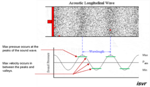
- As sound energy moves through a room the particle velocity within each wave is greatest as the air molecules are in transition between the peaks and valleys of each sinusoidal cycle. (Figure 27)
a. “Most of the absorption comes from the way the sound waves squeeze through the labyrinth of tiny interconnected pores within the material. As the sound moves through the pores, it causes air molecules to drag along the interior surfaces of the material. It takes effort to drag the air molecules across the interior surfaces. This effort turns the vibrations of the molecules into heat, which are then dissipated in the material.” [22]
-
- VB absorption treatments are most effective when the front face of the material is mounted one-quarter wavelength, or greater, from a rigid boundary. Example: One-quarter wavelength of 1,000 Hz is roughly 3”.
a. This recommendation doesn’t mean that a 3” absorber is needed to absorb 1,000 Hz sounds, it means that if you need to absorb a certain amount of energy at that frequency, mounting the front face 3” off the wall will maximize the efficiency and effectiveness of the specified treatment.
b. Also, at 1,000 Hz, the quarter wavelength spacing can be accomplished with a 3” panel mounted directly to the wall; a 2” panel mounted on a pair of 1” fir strips to create a 1” air gap behind; or even a 1” panel, mounted on 2” fir strips.
c. In this example, all higher frequencies (shorter wavelengths) benefit from the optimized efficiencies of the spacing off the wall. It’s only lower frequencies that gradually suffer less efficiency and performance.
-
- Once again, these details aren’t anything architects need to master; just some important concepts to be aware of.
E. VB absorption:
-
- Soft, porous materials have VB absorptive properties, and do not make good PB treatments.
- Because of this wave/ray duality, materials, products, and techniques that effectively absorb sound energy above about 250 Hz are generally least effective at absorbing energy below 250 Hz. The inverse relationship is also true.
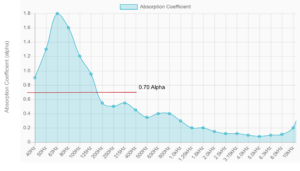
- Regardless of size, type, cost, location, or appearance, all treatment materials are only partially effective at absorbing sound. Each type and thickness has a different absorption coefficient contour (see Part II – Section 4.4). This is a fancy way of saying each material absorbs more, or less, sound energy across the audio spectrum.
- VB Absorption Examples:
a. Mineral wool, rock wool, and spun glass insulation are very useful VB absorption tools when properly specified, located, and installed.
i. Exposed, R-11, R-19 and R-30 batt insulations are effective tools. However, these materials deliver little or no absorption if fully enclosed in a wall, or placed above a hard-lid ceiling. When specified as a sound absorber, these thermal insulation materials must be exposed to the air and sound energy within the room. If necessary for aesthetic reasons, finish with an acoustically transparent fabric, or perforated/slat wall paneling.
ii. Indirect exposure is effective when open vaults, cavities, soffits and traps are created in a room. In these areas, batt insulation can be used to fill cavities, or line walls, as necessary. Additional finish materials are generally not required in areas that are invisible to the public.
iii. If faced, the soft, fuzzy side of the insulation should always be mounted outward, so it’s exposed to the air as much as possible, and not facing the structure to which it is attached.
-
- Not all “insulation” works as an absorber.
a. In the construction trade, the term insulation describes two, structurally different types of material: one is useful to the acoustician; one is not.
b. Closed-cell, Extruded Polystyrene (XPB) rigid foam insulation should never be specified or used as a sound absorber. This rigid foam absorbs little or no sound.
-
- Semi-rigid fiberglass panels are very effective VB sound absorbers too, and one of the most commonly specified types.
a. These products are typically specified with a density of either 3 pcf (pounds per cubic foot), or 6-7 pcf. Other densities exist, but are less commonly required.
b. Fabric-wrapped wall panels, sometimes referred to as “sound soak” panels, are usually constructed from 6-7 pcf fiberglass or rock wool boards. (Figure 28) While maintaining similar MF/HF performance, the thicker the panel, the lower the frequency range of effective absorption. However, LF/VLF performance limitations, aesthetics, and cost often limit the practicality of such panels if they are more than 3” thick.
c. Such panels, commonly sold in 1” and 2” thicknesses, are typically attached directly to a wall, or preferably, furred off the surface by 1”-3”. The furring helps move the front face closer to the max particle-velocity zone at slightly lower frequencies.
d. If you can suspend such panels from the ceiling, as hanging baffles or clouds (Figure 29), they provide extra performance and value because both sides are exposed to the sounds that pass by. Installing such panels as baffles or clouds effectively doubles the square footage of the exposed treatment. A 4’ x 8’ baffle potentially represents 64 ft2 of VB absorptive treatment.
e. Note: Baffles and clouds are essentially the same thing. Baffles hang vertically, while clouds hang horizontally.

-
- Duct liner is an example of a 1.5 to 3 pcf absorption material. It provides useful VB absorption when applied externally, or anywhere in a room that’s directly or indirectly exposed to sound energy. However, when installed inside an air duct, it has little or no impact on the sound energy that strikes the outside of an HVAC duct.
- Be sure to check the fire rating of any/all VB absorption materials you might consider using. Most should have a Class A or Class 1 rating. If you can’t find a lab-tested fire rating report, don’t use it.
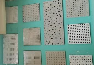
- Perforated panels (Figure 30) are another excellent choice to consider when some amount of absorption is required in areas where hard, smooth, flat and/or concaved surfaces are to be specified.
a. Perforated (perf) panels offer a very effective combination of architectural, aesthetic, and acoustical properties that are hard to ignore. They also offer a blending of all three acoustical tools: very good VB absorption; a modest amount of reflection, and possibly a little HF scattering.
b. To qualify as a VB acoustical surface, there’s one detail to keep in mind: Perf panels must always be mounted with airspace behind them, and that airspace must be lined or filled with un-faced mineral wool, spun glass insulation, or similar absorptive material.
i. Airspace guidelines for medium and large venues: 2″ = bare minimum, 4″ = nominal, 6″ or more extends the frequencies of LF absorption a little. For small rooms, the bare minimum is 1”.
c. Perf panels have a specification labeled “% open area”. This number indicates the percentage of the surface that’s exposed to the absorptive material behind the panel. The higher the % open area, the greater the potential absorption. 20% – 40% open area is the typical range for this application. Regardless of size or shape, the perforations effectively convert a reflective surface into one that’s reasonably absorptive.
d. In addition to gypsum board, perf panels are available in a variety of other material compositions, including: metal (Figures 31 & 38), polypropylene, and fiberboard. The McNichols company is a good resource for perf metal and fiberglass sheeting. [23]
e. There are a wide variety of hole and slot sizes, shapes, and patterns to choose from. Most panel types can be painted, or wrapped with acoustically-transparent fabric, as needed, to best tie in with a room’s color palette and finish schedule.

-
- In most cases, a perforated metal roof deck is a much better solution than a solid metal roof deck. A perf roof deck provides a very large, well distributed, absorption option that will not likely show up as a line item in the acoustical budget.
a. Be sure to specify a sound absorbing filler material, not the XPB-type rigid foam (thermal only) filler.
-
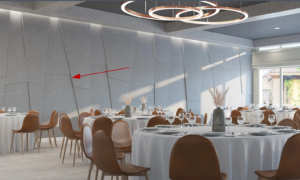
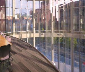
- Micro-perf panels are what the name suggests: panels with thousands of very small pin holes. Figure 32 shows an example of a micro-perf application that solves an age-old acoustical problem of installing an absorptive treatment in front of a glass window or wall.
a. Micro-perf panels come in a variety of materials and finishes.
b. Take care not to fill any of the holes when painting micro-perf panels.
-
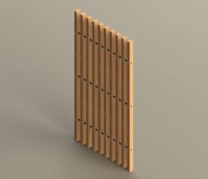
- Slat absorbers (sometimes called diffraction slot absorbers) offer many of the advantages of perf panels, with the added benefit of delivering much greater MF and HF scattering. (Figure 33)
a. Slats can be oriented horizontally, vertically, and diagonally.
b. The width and depth of the slats and gaps determine the frequency spectrum that will receive maximum diffusion/scattering. More on this in Section 6.4 below.
c. Like all perf panels, slat absorbers require that a VB absorptive material be installed behind the slats. The slats themselves only provide finish aesthetics and scattering.
F. Other VB absorption products:
-
- There are many other commercially available VB absorption products. They include open cell foam; spray on cellulose; recycled cotton; bonded wood shavings; polyethylene terephthalate (PET) felt; carpet, open cell metal foam (Figure 34); acoustic plaster; and probably a few more that don’t come immediately to mind.

G. PB membrane/resonant absorption:
-
- LF/VLF energy – exhibiting wave behavior at Fs and below – is most efficiently absorbed using PB techniques and devices.
- There are only a few LF/VLF absorption techniques that are definable and reasonably predictable. The two most widely-accepted methods are classified as a “diaphragmatic” membrane absorbers, and Helmholtz resonators.
a. Though not technically accurate, these PB topologies are euphemistically called “bass traps.”
-
- When sound energy moves through a room its molecular pressure will always be greatest when its long wavelengths reach a rigid boundary. At that point the velocity is essentially zero because – once reaching the boundary – the air molecules at the front of the wave build up and compress, as they briefly stop moving in their original direction. Any reflected energy is forced to change direction.
a. PB treatments are most efficient when mounted flush with, or directly against a rigid boundary such as a floor, wall or ceiling. This puts their membranes within the maximum pressure zones in a room.
-
- Diaphragmatic panels are considered the most effective means of PB absorption. (Figure 35) Such devices are not for the DIY crowd. For proper “tuning” they require very specific sizes, materials, construction methods, and tolerances. Each design modification also requires testing in a very large reverberation chamber to verify performance.
-
- Diaphragmatic absorbers are “limp mass” structures that absorb a moderately- narrow range of reverberation and/or modal energy. They can be designed to perform within a fairly specific range of LF/VLF frequencies. They have the following properties:
a. A rigid, sealed, rectangular box or cavity.
b. Well-defined dimensions and materials.
c. Typical sizes range from 2’ x 2’ x 6” (HWD), up to 4’ x 8’ x 12”.
d. The front face of the enclosure is the “working surface”, which consists of a thin, unperforated panel of wood, plastic, metal, or other flexible material.
-
- When properly constructed and deployed, the vibration of the working surface converts the LF/VLF energy into heat, via the friction that exists between the panel and its mounting attachments; the energy loss that occurs through the mechanical strain and deformation of the flexible panel; the modulation of the internal air spring; and minimization, via cancellation of incoming sound, which is caused by reradiation interferences.
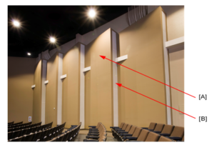
- Note: Gypsum wall board, glass, wood, and metal are also resonant absorbers. While these materials will provide some amount of PB absorption, their low alphas makes them inefficient treatment tools when amplified music is performed or reproduced. (Figures 35 & 36) Such generic construction materials contribute to the overall “room absorption”, but are not generally considered to be primary or remedial acoustic tools.


8. Helmholtz resonators are a cavity-type resonator designed to sympathetically vibrate within a narrow frequency range. A common example of a cavity resonator is an empty soda bottle: the air inside vibrates, and becomes an audible tone when you blow across the top.
a. The main difference between a frequency-specific Helmholtz resonator, and broadband perf panels and slat absorbers, is in the structural captivity of the airspace behind the face.
i. Perf panels and slat absorbers have loose airspace tolerances, meaning they should not have a fully-sealed cavity behind the front face. In this configuration they perform relatively broadband absorption.
ii. Helmholtz resonators require a fully-sealed airspace cavity behind the front face. Like the empty soda bottle, the specific, narrow-band, resonant frequency of that chamber becomes the primary frequency of absorption. Helmholtz resonators are typically specified when trying to tame specific modal frequencies.
b. If fully sealed around all sides and back, slat absorbers become a variation of the Helmholtz resonator.
H. The whole can be greater than the sum of the parts:
-
- Because we often have a variety of absorption needs, it’s possible to design acoustic solutions that have an aggregate effect. To be clear, each treatment isn’t doing more work than it’s capable of, but rather each treatment location can accomplish the work of multiple tools. (Figure 38)
I. Architectural finish materials:
-
- Commercial grade carpet is a marginally effective VB absorber. It also has four significant advantages: cost, aesthetics, location, and performance.
a. Cost: Carpet rarely appears as a line item in the acoustics budget. Therefore, if already planned, it becomes an “acoustical treatment” that adds no additional cost to the owner.
b. Aesthetics: In almost all cases, there are only two finish options for flooring: hard and soft. Carpet is the ubiquitous, soft finish material, and is pretty much the only option if a VB absorption product is required. Very few people are offended by the application or appearance of carpet. Well, to be honest, I’ve been in a few hotels and casinos that had aesthetically offensive carpet, but that’s a whole ‘nother topic.
c. Location: Carpet often covers large areas, as well as being evenly distributed throughout a room. Even spot or area applications can be useful.
d. Performance: While of little help in the LF/VLF spectrum, carpet can make a noticeable difference in the range of frequencies that impact speech intelligibility. However, at best, a fully carpeted room will only help reduce some of the worst intelligibility and ambient noise problems. When no other VB absorption is planned, carpet alone should not be considered an appropriately-sufficient acoustical solution.
i. While underpadding slightly adds to the performance, it’s usually not a feature or expense that’s mandatory.
e. When the primary use of a room or venue is geared toward unamplified sound, carpet should not be installed in music practice/rehearsal rooms, on stages, or in choir lofts. This is because many acoustic instruments have a significant amount of contributory sound energy directed towards the floor. Similarly, carpet is not recommended below seating in worship facilities since voice sound levels are reduced, which negatively affects the corporate worship experience.
-
- Padded seating: Whenever possible, especially in medium and large venues, incorporating padded (preferably soft fabric seat and back) seating should be given serious consideration. Padded seating provides another common finish that helps mitigate one major acoustical problem in some venues.
a. The problem is the dramatic changes in reverberation times that occur when attendance varies greatly from one event to the next. There is no simple, mechanical, nor electroacoustical solution for this scenario.
b. If carpet is not part of the plan, specifying fully-padded seating is an extremely helpful alternative.
c. For most venues, if you have to choose one over the other, choose padded seating over carpet. In many cases, doing both is ok too.
-
- Fabrics: The phrase “acoustically transparent” is used to describe fabrics that do not alter, impede, or absorb sound energy. When used as a finish covering for the various sound absorption materials listed above, it’s critical to specify acoustically transparent (AT) fabrics. Guilford of Maine [25] offers one of the widest selections of AT fabrics.
a. If you need to specify fabrics for aesthetic reasons, use AT type so the material doesn’t contribute acoustically. Typically, AT fabrics are not meant to be draped.
b. If you want, or need to apply fabrics for their absorptive properties, it’s usually best to use heavy (14-18 oz. per sq. yd., or greater) velour-type materials, gathered to half area.
J. There is one universal variable to the effectiveness of all VB and PB absorption products, which is the thickness or depth of the treatment. Thicker, deeper materials generally absorb more sound, and reach down to lower cutoff frequencies. But, more is not always the goal. Too much, or the wrong type of treatment, can be a problem too.
-
- See my Parametric Acoustics commentary here. [26]