6.4 Diffusion: The physical process of diffusion causes reflected sound energy to be spread out in a room. Our detailed understanding of this phenomenon is only about forty years old. The theories used today were developed by Dr. Manfred Schroeder [20], circa 1970, but weren’t codified and brought to market for the first time until the early 1980s.
A. You have no doubt noticed that the words diffusion and scattering have been used throughout Section 6.0. Diffusion and scattering are closely related subjects, but their net results are somewhat different. The details of the differences go beyond the basic needs of this commentary, but here are the key points.
B. When sound waves strike rigid convex or geometrically-complex structures (Figure 39) they burst into countless smaller reflections, which are then randomly “scattered” in many directions. Visualize a beam of light that’s scattered when it strikes a disco ball.
-
- Random scattering implies no specific spatial or temporal controls have been implemented.
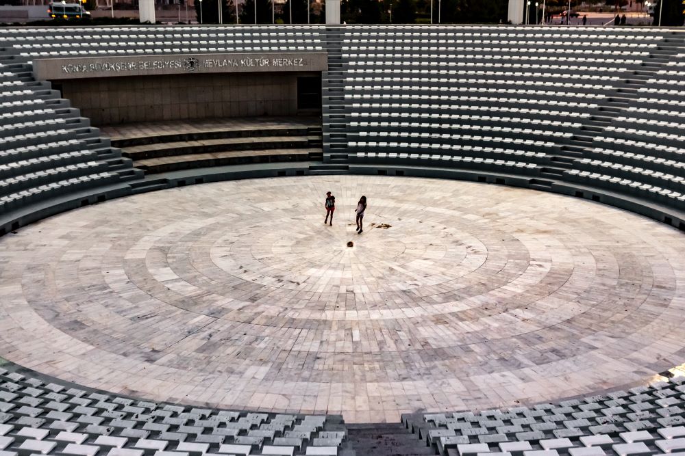
- Common architectural elements that scatter incident sound are stairs, stages, chairs, pews, cylindrical pillars, balconies, statuary, and all other complex geometric elements and curved surfaces that present in a convex manner.
- Bottom line: Architectural elements that scatter sound are highly desirable, and rarely problematic.

C. While round columns and other convex structural features (Figure 40) make excellent scattering structures, this is not true of concave structures. Once again, convex features scatter sound; concave features “focus” sound; often detrimentally.
-
- Bottom line: Architectural features that focus sound are rarely desirable.

D. When sound waves strike custom-built diffusion modules (spelled diffusors or diffusers) they are scattered in fairly even and predictable directions. Size, depth, and geometric topology all factor into the various types of custom diffusors. Figure 41 shows an example of a QRD (Quadratic Residue Diffusor) diffusor. QRD designs are based on mathematical number-theory sequences developed by Manfred Schroeder.
-
- Much of the diffused sound energy is still “alive”, and actively moving through the room. However, small amounts of energy also get trapped, and absorbed, in the complex geometry of the diffusive boundary.
- Diffusion is a frequency-specific treatment methodology. The larger the wells and cavities in a diffusor panel, the lower the frequency range that is effectively diffused. Smaller wells and cavities are used to better diffuse and scatter higher frequencies.
- When properly defined and implemented, diffusion is a highly desirable treatment tool. Architectural features and finishes that diffuse and scatter sound provide a uniquely beneficial hybrid of sound control; they break up problematic slap and flutter echoes, and absorb some of the energy that’s being scattered, while also allowing a reasonable amount of reverberant energy to be maintained.

E. LF and VLF scattering is accomplished by deploying large, moderately-complex geometrical shapes. Figure 42 shows a custom ceiling treatment that is dimensionally large enough to provide broadband scattering.
-
- The wavelength of a 100 Hz tone (approx. fundamental of a baritone voice) is a little over 11’. A low, bass guitar note (50 Hz) is double that wavelength. Because the wavelengths are so long in this region, LF and VLF scattering requires treatments that are many times larger than what are needed for MF and HF diffusion/scattering.
a. It’s not necessary to construct full-wavelength LF or VLF scattering elements. However, to be effective, at least one-quarter of the target wavelength is needed.
b. A convex structure that’s at least 5.5’, in its smallest dimension, can provide useful scattering for frequencies of 50 Hz and above. A solid stage, with a 3’ elevation, will provide a little scattering down to about 95 Hz.
-
- For most public facilities, large building features or structures are often the only practical application of LF/VLF scattering. For some rooms large structural protuberances, or ceiling clouds, can serve this purpose. In others, providing there is sufficient mass, balconies, pews, chairs, and stairways can each contribute to LF/VLF scattering.
- In summary, diffusion/scattering elements are very effective tools when properly applied. They can also be more expensive to implement than either of the other two tools.

6.5 Surface Area and Location Challenges:
A. Regardless of the acoustical tools or materials used, installing the appropriate amount of each material is critical. In their book, “Acoustic Absorbers and Diffusers”, world renowned acousticians Trevor Cox and Peter D’Antonio summarize it this way: “Good acoustical design results from an appropriate combination of absorptive, reflective and diffusive surfaces.” [27]
B. The successful application of any new or custom treatment is based on the total surface area of each material or product, and the locations in which they are placed. The formula used to calculate a room’s reverberation time (T60) relies heavily on the total surface area of each finish material applied. However, grouping the materials together on one wall, or in one confined area, is usually not fully productive, recommended, nor cost effective.
6.6 Architects: Is Pure Random Accident Part of Your Business Model?
A. When a room is built without a specific acoustical plan, its baseline acoustical characteristics are defined by its volume and geometry, the finish materials used, and its furnishings. Typically, these are materials such as: carpet, drapes, blinds, sheetrock, glass, padded or un-padded chairs, steel, wood, tile, concrete, and acoustical ceiling tiles. All are owner- and architecturally-driven decisions.
-
- While some may be quite similar, the acoustical properties (absorption and/or scattering coefficients) of each material is different.
- The greater the total square footage for each material, the more it will influence the overall reverberation and resonant (modal) decay times, and the tonal character of a room. Therefore, by pure random accident it’s possible to build a venue that is too “wet” (reverberant), too “dead” or “dry” (non-reverberant), or something that’s decent for some applications. Architects: Is “pure random accident” part of your business model? Life safety and code requirements prompt you to work out proper lighting and HVAC systems, why not apply similar time and energy looking into the acoustical ramifications of your design?
- For new construction, the only way to avoid straying into a randomly accidental end product is to include an acoustician that can advise, specify, and if necessary, predictively model the acoustical repercussions of your design choices.
- If you believe additional acoustic treatment is required for an existing venue, it’s important to properly measure the current conditions, and calculate and evaluate the quality, quantity, type, and physical location options for each new material. Using the wrong treatment type, or an insignificant amount of new treatment, will likely be ineffective, and potentially a huge waste of money.
B. General, and/or specialized, acoustic treatment(s) should be considered under these conditions:
-
- Good to excellent speech intelligibility is a clearly-defined deliverable.
- Ambient background noise is, or may be, a problem.
- Live, acoustic, and/or amplified music will be performed.
- When characterizing the most demanding uses for a room, you believe the whole room may need to be adjusted to a more appropriate reverberation time (Tmid), and/or “Slope Ratio” (TSR). [28]
a. An obvious example occurs when an old, traditional church sanctuary is being converted (modernized) to accommodate today’s highly-amplified contemporary worship music.
-
- Acoustical zones or spot treatments are required.
a. There are situations that may require a small, dedicated, acoustical zone that differs from the overall room requirement. A choir loft or drum kit enclosure are two possible examples.
b. There are also scenarios that call for a spot treatment with absorptive or diffusive materials (Figure 43) in order to mitigate a localized problem in an otherwise well-behaved room.

6.7 Feasibility:
A. At its most fundamental level, successful acoustic design boils down to these basic feasibility questions: What is the primary use for the space? Where can (or can’t) we consider putting treatment? What does the treatment look like? How much does it cost?
B. For the owner and/or architect, these questions require no technical background to answer. And to anticipate one of the most frequently asked questions: “Do we really need to even talk about acoustics?” The answer will almost always be, “yes.”
C. For the consultant, the answers will clearly guide the general scope of work and budgetary estimates. For more on this theme, see Applied Acoustics Requires Feasibility & Creativity here. [29]
6.8 Accountability:
A. Developing a comprehensive acoustic design is an exercise in calculated probabilities. Even under ideal conditions there are simply too many variables and unknowns for precise results.
B. For most projects, a consultant’s specifications will define treatment materials and techniques that are based on lab-tested data, published performance specifications, computer modeling, best practices, and decades of experience. From there, the significant variables and unknowns include:
-
- The lack of a well-defined scope of work proposal that clearly establishes the primary uses and acoustical goals for the venue.
- The owner’s and architect’s willingness to accept and implement the consultant’s recommendations.
- Ill-advised “value engineering.”
- Poor installation practices.
- A small margin-of-error that exist in all acoustic modeling applications.
C. Because of the above, consultants cannot, and should not guarantee precise results. Look for consultants that commit to providing a good faith effort to direct and achieve – as best as possible – the stated acoustical goals set forth in their proposals and scope of work documents.
D. Compromise should also be a part of the conversation. I would rather see 70-80% of a design implemented, than 100% be rejected because any or all of the feasibility issues are unresolvable.
-
- At 70-80% implementation, noticeable improvements can be achieved and documented. From there, future plans can be made for additional treatment.
- Pay for a design that provides – what is estimated to be – the 100% solution. Then, if necessary, let the consultant prioritize any cuts needed to meet the immediate project goals. This approach offers a clear path forward for any future treatments that may be deemed necessary.
6.9 Electronic Solutions:
A. Please notice that loudspeakers are not one of the acoustical tools listed above.
-
- Loudspeakers are additive devices; they add sound energy into a room.
a. The best that loudspeakers can do is minimize the amount of unusable energy they broadcast into a room. This is accomplished through the accurate selection and placement of all loudspeakers, and properly managing the timing and directivity of their sound propagation.
-
- Most acoustic treatments are subtractive materials and devices; they capture or otherwise reduce sound energy that has been generated by loudspeakers, people, musical instruments, or other mechanical devices.
7.0 WHERE DOES ALL THE UNUSED SOUND GO?
7.1 Once initial sounds get started, and move into a room and past the ears of the audience, do they go on forever? If not, why not? The answer is no, they don’t last forever.
7.2 The basic law of conservation of energy states that “energy can be transformed, but never created or destroyed.” This means that all the energy a sound source puts into an enclosure must be accounted for by either absorption (turning into heat), transmission (passing through the enclosure to another space), or reflection (adding to the sound level). [30]
A. If sound energy were to build up in a completely sealed, totally reflective room, and the sound source continued to put out sound energy, none of the energy would be absorbed. “Over time, we could theoretically arrive at a pressure that would be explosive.” [30]
7.3 Presuming an enclosed space, when sound energy reaches any absorptive or diffusive boundary, barrier, object, or person, regardless of size, some or much of its energy is captured and exhausted. The remaining energy is either reflected and/or scattered – continuing on its new path(s) until it strikes other objects – or is transmitted out. This process continues until the remaining sound energy becomes inaudible, then completely gone.
A. The physics: In simplistic terms, friction is the mechanism that converts sound energy into heat. Heat is inaudible. This all happens at extremely small human scales. You really can’t see the movement or feel the heat, but it’s there.
B. Even without absorptive and/or diffusive materials, sound energy is ultimately depleted by the friction that exists between air molecules as they are pushed and pulled through the air.
-
- Air absorption consumes HF energy the most. This explains why, in most rooms, finding excess reverberation above 2 kHz is rarely a problem.
a. Along with the mass of the walls, floor, and/or ceiling, it’s also one of the reasons why you hear the LF/VLF energy from the neighbor’s party in significantly greater amounts than the MF/HF sounds.
C. One other important factor exists: sound transmission that passes through walls, floors, and ceilings.
-
- The construction materials and techniques used in most buildings allow a certain amount of sound to escape the structural envelope. This is generally not by design, nor is it necessarily a good thing, however it is one more way that sound energy is depleted.
7.4 What About Outdoor Sound?
A. Air, various natural and man-made structures, and distance all play significant roles in the absorption, reflection, diffraction, and scattering of sounds as they propagate outdoors. Primarily, there are six controlling factors:
-
- The Inverse Square Law (Figure 44) explains the dissipation of sound pressure at the rate of 6 dB per each doubling of distance. The initial wave of energy spreads out more and more as it moves away from its source. Therefore, less and less energy is audible at various points along its flightpath.

-
- Depending on the surrounding structural and environmental conditions, sound energy may encounter any number of boundaries and/or resonant objects. Such items further dissipate sound energy when contacted.
- Ground reflections and/or absorption. These depend on what substance(s) covers the surface.
- Large standing or seated audiences provide some ground-level absorption.
- Generally speaking, there are no room modes outside. The resonant peaks of modal energy found inside a room don’t build up and linger over time.
- Some additional losses occur, and vary, based on wind direction, temperature, and humidity. Eventually the sound pressure is sufficiently reduced to a point where it falls below our threshold of hearing.
C. Outdoors, LF and VLF frequencies also follow the Inverse Square Law, but they generally maintain audibility over greater distances. There are at least three controlling factors for this behavior:
-
- Air absorption is less and less efficient as frequencies decrease, and wavelengths get longer. This explains why LF/VLF sounds seem to travel further before being inaudible.
- Ground reflections. Because the LF/VLF wavelengths are so large, there is rarely much absorption achieved by most ground covers.
- And once again, some amount of additional loss occurs, and varies, based on wind direction, temperature, and humidity. Eventually the LF/VLF sound pressure is sufficiently reduced to a point that it falls below our threshold of hearing.
Final Thoughts:
That’s it for this episode. Hopefully, you’ve learned a few things you didn’t already know, and are looking forward to what comes in the next installment. In Sections 8 and 9 we’ll cover Room Geometry and Acoustic Shadowing.
One of the implications of this commentary is to encourage architects to put as much time, effort, care, and awareness into implementing good acoustics in their room designs as they put into satisfying their customer’s needs for good lighting, heating, and air conditioning.
If you remember nothing else from this series, please remain focused on this: For better or worse, every architectural shape, feature, position, and finish influences sound behavior and quality, and ultimately – the human experience.
References:
[20] https://en.wikipedia.org/wiki/Manfred_R._Schroeder
[21] Architectural Acoustics – 2nd Edition; Marshall Long; pg. 327; Elsevier Academic Press
[22] Choosing & Using Porous Absorbers – Trevor Cox – Sound on Sound magazine – July 2015 https://www.soundonsound.com/reviews/choosing-using-porous-absorbers
[23] https://www.mcnichols.com/perforated-metal
[24] https://www.afmg.eu/en/ease-enhanced-acoustic-simulator-engineers-overview
[25] https://www.guilfordofmaine.com/acoustic
[27] Acoustic Absorbers and Diffusers: Theory, Design and Application. Trevor Cox and Peter D’Antonio https://www.taylorfrancis.com/books/mono/10.1201/9781315369211/acoustic-absorbers-diffusers-trevor-cox-peter-antonio
[28] Acoustic Essentials for Architects – Part II – Section 5.4.C.2 https://www.prosoundweb.com/acoustic-essentials-for-architects-common-terms-and-clarifying-differing-reflective-sounds/1/
[30] Sound System Engineering, Second Edition. Don and Carolyn Davis. Howard Sams & Co.
[31] https://en.wikipedia.org/wiki/Inverse-square_law. Graphic credit – By Borb, CC BY-SA 3.0, https://commons.wikimedia.org/w/index.php?curid=3816716
Peer Review Team
A special thank you goes out to Neil Shade, FASA (Acoustical Design Collaborative), Charlie Hughes (Biamp and Excelsior Audio Labs), and Rob Miller (Threshold Acoustics) for assisting with notes, comments, and corrections that made this work presentable.