

Unsure about phantom power? Let’s clear up the mystery. Nearly all mixing consoles and audio interfaces provide phantom power at their microphone input connectors. Most condenser mics need phantom power to operate, so you simply plug the mic into the mixer to power it.
But the ways we use and connect phantom power can make a big difference in how well those mics work. So what, exactly is phantom power, and how do we apply it effectively?
Understanding It
Phantom power is DC electrical power that is sent to a condenser mic through its balanced mic cable. The mic receives power from, and sends audio to, an audio device along the same wires. It’s called “phantom” because the power does not feed through a separate wire; it’s “hiding” in the mic signal wires inside the mic cable.
Phantom power can be built into these devices:
• Mixing consoles
• Mic preamps
• Audio interfaces
• Stand-alone phantom power supplies
• Instrument amps with an XLR mic input
In all cases the phantom power appears at a female XLR mic input connector. Technically, phantom power is a positive voltage (12-48 volts DC) on XLR pins 2 and 3 with respect to pin 1. Pin 1 has 0 volts; pins 2 and 3 have the same positive DC voltage.
So there is no voltage between pins 2 and 3. The cable shield is connected to the phantom-power ground via pin 1. Also, pins 2 and 3 carry the balanced audio signal.
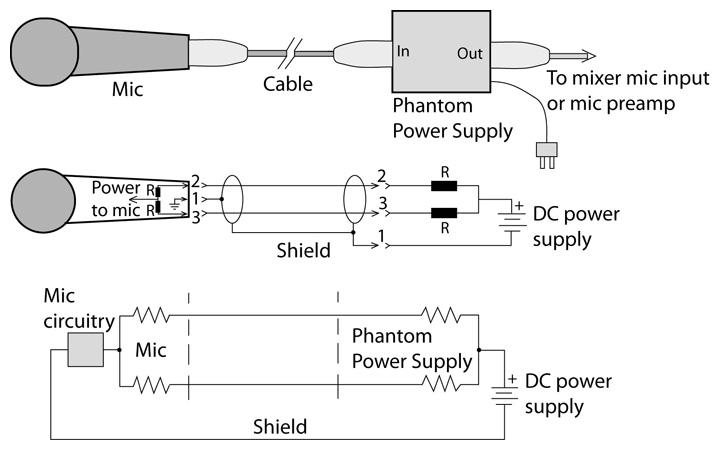
Figure 1 (top) shows a microphone plugged into a stand-alone phantom power supply. Inside the phantom supply (Figure 1, middle) are two equal resistors (R). They supply equal voltage to pins 2 and 3 with respect to the pin 1 ground. Inside the mic, phantom power is tapped off two equal resistors (or a center-tapped transformer). Figure 1, bottom, shows how the phantom current travels through the mic cable from right to left:
1) The current leaves the DC power-supply positive terminal and goes through two equal resistors.
2) The current travels along the mic cable signal conductors to the mic.
3) The current is recovered inside the mic and goes through the mic circuitry.
4) The current returns to the DC power-supply negative terminal via the cable shield.
The audio signal appears across pins 2 and 3, and feeds the mic preamp through some DC blocking capacitors (not shown).
The international standard IEC 61938 defines three voltages and circuits of phantom power called P12, P24, and P48. A 48-volt supply uses two 6.8K resistors to feed power to a mic.
In both dynamic moving-coil and ribbon mics, the voice coil or ribbon is not connected to the pin 1 ground. So no phantom power can flow through the voice coil/ribbon because there is no return path for the phantom current.
However, if the mic element is accidentally shorted to pin 1 or to the mic housing – say, by a miswired XLR connector – current can flow and damage the mic. For this reason, it’s safer to switch off phantom power for dynamic and ribbon microphones.
Some new ribbon models have a built-in preamp that works off phantom power. Many active direct boxes are phantom-powered as well. This often confuses musicians, who think that the DI provides phantom power. It doesn’t.
Finally, according to our old friend Wikipedia, “Digital microphones complying with the AES 42 standard may be provided with phantom power at 10 volts, impressed on both audio leads and ground. This supply can furnish up to 250 mA to digital microphones.”
Using It
Now that we know what phantom power is, let’s explore its use. With the master faders turned down in the mixer, turn on phantom power. The phantom on-off switch in many consoles is labeled “P48” to mean “phantom power 48 volts,” or it might be labeled “48V” or “Phantom.” Mute a mic channel and plug a mic into that channel. This prevents a loud pop when plugging in the mic. Unmute the mic and wait a few seconds for it to be fully powered.
Some mixers apply phantom to all input channels at once; in others, phantom is switchable on each input. That lets you turn off phantom for ribbon mics as a safety precaution. A few mixers apply phantom to only a few channels, so be aware of that if you can’t power-up a mic. At gigs, musicians may bring their own mics, DIs or preamps – be sure to ask them if their device needs phantom.
Mics with inline on-off switches typically short XLR pins 2 and 3 to mute the mic. Since the same phantom voltage is on both pins, there is little or no pop when the pins are shorted together. If you hear a pop when switching the mic, the phantom voltage is slightly different on the pins due to the resistor tolerance in the phantom power supply. Some on-off switches short the pins over a time constant, preventing pops. If you need to block phantom power in one channel, use blocking capacitors or a 1:1 isolation transformer.
Stand-Alone Supplies
What if your mixer, mic preamp or instrument amp doesn’t have phantom power? Acquire a stand-alone supply (Figure 2) and connect the supply in series with the mic cable. Some phantom supplies are AC powered, some are battery powered, and some are both. Some can power a single microphone, others can power several at once.

A few supplies have a switch that selects 12- or 48-volt phantom power. Set it to 48-volt for more headroom if the mic is specified for 48 volts.
The supply has XLR input and output connectors, one pair per channel. Connect a mic cable between the mic and the supply’s input connector. Plug another mic cable between the supply’s output connector and the mixer, preamp or instrument amp’s mic input.
If the amp’s input connector is a 1/4-inch phone jack – not an XLR – insert a transformer adapter (Figure 3) between the phantom-supply output and the amp’s input jack. This fosters powering a condenser mic and plugging it into an instrument amp that lacks phantom power. (Many solo performers use this approach.)

Taking Precautions
As noted earlier, don’t plug a condenser mic into a turned-up input with phantom already switched on, or you’ll hear a loud pop. If there’s no choice (as during a live concert), mute the mic channel before plugging in the mic.
Also, make sure the phantom voltage is adequate for the microphone. Check the data sheet under the “powering” spec to see what it requires. Some mics start to distort or lose level if phantom voltage drops much below 48 volts. To measure the phantom voltage at your mixer’s mic input, use a DC voltmeter to measure between XLR pins 1 and 2. Do the same between pins 1 and 3.
The amount of current available from a phantom-powered mic input is often an issue. Condenser mics draw a certain amount of current – up to 10 milliamps (mA) in some models. The phantom power supply must provide as much current as the mic draws, or else the mic will distort at a lower SPL than is specified in its data sheet, or the mic will not work at all.
The original DIN 45596 standard specified that a phantom power supply should provide a maximum of 2 mA. Some portable or low-cost cost gear might supply only 1 or 2 mA.
The new IEC standard specifies a maximum current source of 10 mA for each microphone. If an audio device provides less than 7 mA simultaneously at each powered input, IEC 61938 requires that the manufacturer state the amount of current their device provides.
In addition, be aware of phantom voltage sag. Microphones draw current through the phantom supply’s resistors, and that current causes a voltage drop E = IR across each resistor. The higher the current drain of a microphone, the more it drops the phantom voltage at the mic connector. Current drain is usually specified in the mic’s data sheet.
If a condenser mic doesn’t work due to a low phantom voltage after the mic is plugged in, try one of these suggestions:
• Supply phantom from a better regulated console.
• Plug the mic into a well-regulated stand-alone supply, and connect it to a mixer mic input with phantom turned off in that channel.
• Use a mic with less current drain or with lower phantom voltage requirements.
Phantom power supplies should be rated in the total number of milliamps they can supply, but few manufacturers offer that spec. Make sure that the total current drain of all the mics in use doesn’t exceed the supply’s current rating (if available).
It’s also a good idea to avoid having phantom power in a patch bay because someone is likely to patch in and cause a pop. If you must patch into a jack with phantom on it, mute the input module that the mic is connected to. (Mic-level patches should be avoided anyway.)
Some phantom supplies cause a hum when plugged into an XLR connector that ties the shell to ground. Float the shell. This also helps to prevent accidental ground loops. Since the cable shield carries the DC return, be sure the shield and its solder connections are secure. Otherwise expect crackling noises – especially when the cable is moved.
Some mics work either on internal batteries or external phantom power. In most designs, connecting the mic to phantom automatically removes the battery from the circuit. Otherwise the battery would severely load down the phantom supply. If this appears to be happening, remove the battery or turn off phantom in the mic’s channel.
Employing Splitters
Applying phantom power correctly is important when you use a mic splitter, which sends a mic signal to two or more destinations; for example, to a FOH console, monitor console, and recording mixer. A simple splitter is a Y-cable, while more elaborate splitters are transformer isolated. Inside the splitter, the input XLR is wired to a 1:1 transformer (Figure 4).
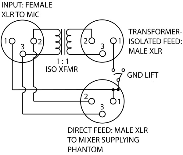
The splitter in Figure 4 has two feeds or outputs: one direct and one isolated. Wired directly to the mic input connector, the direct XLR output connects to the mixer that supplies phantom power. Only one mixer should be the phantom source.
The transformer-isolated XLR output connects to another mixer. Since the transformer electrically isolates the two mixers, phantom power from one mixer can’t get into the other mixer. Neither can any radio frequency interference (RFI). Ground-lift switches in the splitter are used to prevent ground loops between two or more mixers.
It’s essential to set up phantom power correctly when using a splitter. Decide which console you want to supply phantom power (usually FOH). Connect the splitter’s direct outputs to that mixer’s snake.
Splitters have a ground-lift switch on each output channel. This switch connects or disconnects (floats) the cable shield from pin 1 of the XLR connector. When the ground-lift switches are set correctly, you should get no ground loops and their resulting hum.
To set ground-lift switches:
1) Turn off phantom power in each mixer, and turn down all faders.
2) Make sure the direct feed’s ground-lift switches (if any) are set to ground, not lift. Otherwise phantom power won’t work.
3) Go to the mixer connected to the direct feed. Turn on the mixer, switch on phantom power, and bring up each fader to listen for a signal.
4) On the splitter, find the ground-lift switches for the other mixer’s feed. Set them to the position where you monitor the least hum and buzz at the other mixer.
5) Repeat step 4 for any additional mixers.
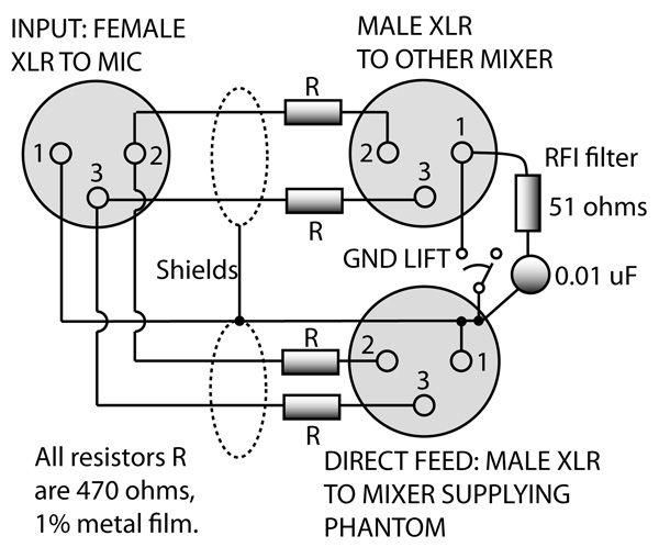
To save money, some use Y-splitters (Figure 5) instead of transformer-isolated splitters. The resistors shown in Figure 5 prevent mic loading and improve isolation, while the ground lifts prevent ground loops and block phantom power. Some engineers prefer to omit the resistors. Unlike a transformer splitter, a Y-splitter does not block RFI.
DC Bias
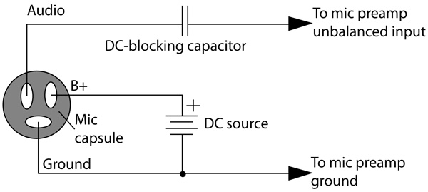
Some mics or capsules work on “DC bias” or “plug-in power” rather than phantom power. Suppose the mic capsule has a built-in FET source follower with three terminals: audio, power and ground. In this case, a separate wire supplies a DC voltage to the mic capsule (Figure 6).
This approach is used in lavalier, hanging, and clip-on instrument mics. They have a mic capsule joined to an XLR connector by several feet of cable. The mic capsule itself runs off DC bias, while the XLR connector houses a circuit that runs off phantom power. That circuit converts phantom power to DC bias for the mic capsule.
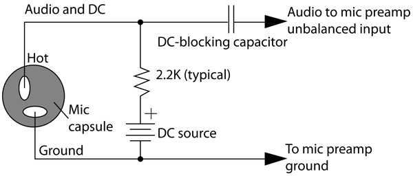
Electret mic capsules can be powered directly by DC bias from a 1/8-inch phone jack. On the tip and ring, +3 to +5 volts is supplied, while the sleeve is the supply ground. This 2-wire powering arrangement is used in many portable recorders and computer sound cards. The DC power is fed typically through a 2.2K resistor, and a capacitor blocks the DC from the mic preamp input (Figure 7).
Plug-in power is often incorrectly called “phantom power” in marketing literature. Be sure not to confuse them. Phantom powering requires a balanced connection; plug-in power is unbalanced.
There’s a lot to know about phantom power. If you’re unsure about it’s use and application, keep this article handy.