
Loudspeaker modeling files are most often used with acoustical modeling programs such as (AFMG) EASE, Focus, CATT-Acoustic, and others to help determine how well the loudspeakers cover the audience areas and how much “spill” there is on the room’s surfaces.
Some of these programs also allow for the investigation of additional metrics like reverberation time, clarity, speech transmission index (STI), and more.
For many of these items, it’s important to have accurate data about the characteristics of the loudspeakers used in the models. Errors in the data will often lead to errors in the results the programs generate. It’s also possible to use some of the modeling files to help optimize the design of crossover filters for loudspeaker systems.
Since the files have both on-axis and off-axis data, the effects of the crossover and equalization filters used for each pass band can be seen in the overall directivity response of a loudspeaker. (I’ll be providing an example of this in a follow-up article.)
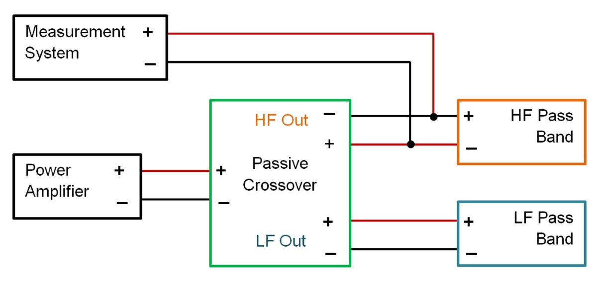
While it’s sometimes possible to measure a multi-transducer loudspeaker system as a single radiating, full-range device, these measurements may be limited in their use. We certainly cannot employ them to help design the crossovers for loudspeakers. It’s preferred that each separate pass band of a loudspeaker is measured individually, when possible. Measurements are best performed with no filters in place, which allows the natural response of the drivers mounted in their enclosure to be captured.
There are some loudspeakers that don’t allow for these separate pass band measurements, and this can be a result of their design or operation. Each type of loudspeaker must be evaluated as to how it functions acoustically. It’s only possible to measure each pass band separately if each one actually radiates acoustical energy separately from the other pass bands.
Measurement Distance
The first thing to do is to make sure the measurements are made in the far-field of the device being measured. Too often, I hear people indicating they perform measurements at 1 meter (m). After all, that’s the standard distance, right? Wrong!
For all but very small loudspeakers, a distance of 1 m is way too close. That distance is still most likely in the near-field of the loudspeaker, and in the near-field, the frequency response can change as a function of distance from the device.
In the far-field, on the other hand, the frequency response of the device will not change. Although air absorption can occur at higher frequencies when the measurement distance is relatively large, it’s typically not a concern for the measurements being performed.
The far-field of an acoustical radiator can be a function of both its size and the frequency (wavelength) which it radiates.
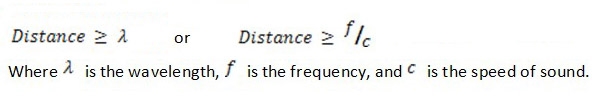
In the low frequency region the distance at which the transition from near-field to far-field occurs is dependent only on the wavelength radiated.
Equation 1 shows that measurement distance needs to be at least one wavelength away from the device.
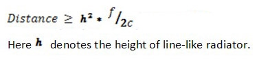
In the high frequency region the distance at which the transition from near-field to far-field occurs is dependent on both the size of the source and the wavelength radiated. For a line source, or a source that is like a line, the transition distance is given by Equation 2.
For non-line source devices like pistons, cone drivers, and horns, the transition distance is given by Equation 3.
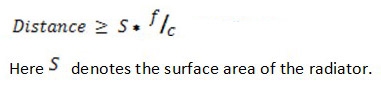
These devices have appreciable surface area and/or a relatively low aspect ratio (height/width).
When evaluating S for a loudspeaker, it’s usually best to include the entire front surface of the loudspeaker, not just the surface area of drivers themselves. This is necessary to account for the diffraction that occurs at the edges. These, too, are sources of radiation that are generally excited by woofers, midrange drivers, and dome tweeters.
Let’s look at an example loudspeaker and see how far away we need to be for far-field measurements.
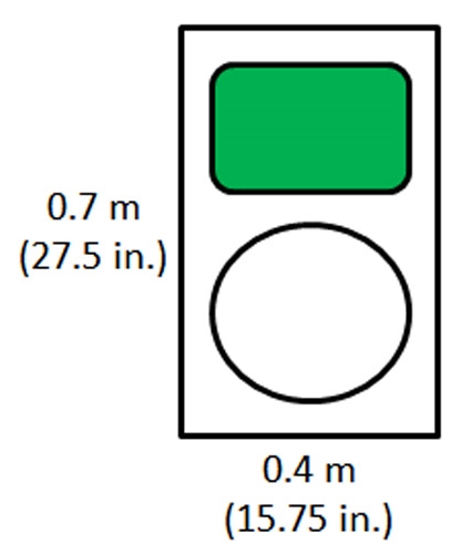
Figure 1 shows a loudspeaker with a height of 0.7 m (27.5 inches) and a width of 0.4 m (15.8 inches), and it uses a horn-loaded HF pass band and a direct radiator LF pass band.
A rough rule of thumb often used for the measurement distance is 3x the baffle diagonal, which is about 2.4 m (7.9 feet) and is shown by the purple line (Figure 2).
In addition, the red curve is the minimum distance as defined by wavelength only, the blue curve is the minimum distance as defined by the source size (the entire baffle area), and the green curve is the minimum distance required when we consider only the area of the HF horn mouth. Because the horn has good directivity control at high frequencies, it’s radiation is not “illuminating” the baffle edges, meaning that we can typically use this distance in such cases.
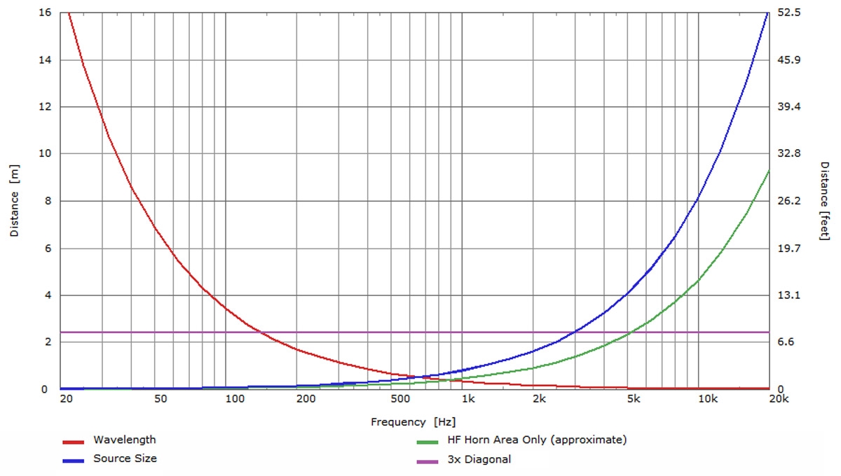
The curves in Figure 2 demonstrate that the 3x diagonal rule of thumb ensures we’re in the far-field from only about 150 Hz to just above 5 kHz for this loudspeaker. If accurate data is needed up to at least 10 kHz, the measurements need to be performed at least 4.7 m away from this loudspeaker.