
We are all familiar (or at least should be) with a low-pass and high-pass filter.
As the name implies, they pass one part of the audio spectrum while attenuating the others. They are the basis for loudspeaker crossovers.
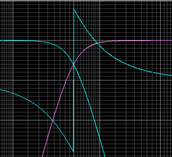
As with any analog filter there is phase shift associated with the change in output magnitude of these filters.
Examples of these are shown in Figure 1 (below) as fourth-order Linkwitz-Riley filters. If we were to add the output of these filters back together, essentially combining them with a unity gain mixer, we would get the response in Figure 2 (also below).
Here we see that the magnitude response is perfectly flat; it passes all portions of the audio spectrum, thus the name all pass.
However, the phase response is not flat. There is phase shift associated with this all pass behavior.
This phase shift is due to the contributions of the low pass and high pass filters that were combined (mixed). There are, of course, other ways to construct all-pass filters.

They can be defined mathematically, just as low-pass and high-pass filters can be. They can be of different orders (i.e. first, second, third, etc.) and have specific alignments (Butterworth, Bessel, Linkwitz-Riley, etc.).
These alignments are not defined by the shape of the magnitude response at the corner frequency of the all pass, as we typically think of low-pass and high-pass filters, but by the shape of their phase response at the corner frequency. Low-pass and high-pass filter alignments can also be defined this way.
One difference to remember about all pass filters is that for each order there is 180 degrees of total phase shift. Low pass and high pass filters have only 90 degrees of total phase shift for each order. The importance of this distinction will become clear later.

Now that we have a basic understanding of an all-pass filter, let’s see how one can be put to good use. Suppose that we have a two-way loudspeaker system comprised of a high-frequency horn and dual 12-inch woofers as illustrated in Figure 3.
The horn is located at the top of the baffle. One woofer is directly below the horn. The second woofer is directly below the first. This is a fairly typically configuration.
To keep things simple we will model these components as point sources. This will make it easier to see anomalies in the directivity response of the system when the individual sources are combined.

The horizontal symmetry of our example loudspeaker assures us that nothing spectacular will occur in the horizontal plane. Having the sound sources displaced vertically will yield some interesting behavior.
Since all of the good stuff will happen in the vertical plane we will be looking primarily at vertical directivity maps and a few polar plots.
The nice thing about a directivity map is that it allows us to look at the relative level of different radiation angles at all frequencies at the same time, whereas polar plots only allow us to see the relative level of different radiation angles at a single frequency.
Ideally we should see the same level at all frequencies and at all angles since we are using point sources (which have no inherent directivity).