I certainly don’t want to try to cover an audience area with a loudspeaker system that suffers from horizontally asymmetry over only a portion of its pass band. This asymmetry of the directivity response is not caused by one of the woofers having more output than the other.
The bottom woofer is the one that has been attenuated and the main lobe is pointed down, not up. This lobe and its asymmetry are caused by the phase shift introduced by the additional low-pass filter we put on the bottom woofer. The bottom woofer now has a different, and non-complementary, phase response compared to the top woofer and the horn.
To correct this all three components need to have complementary phase response.
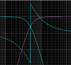
We need to add phase shift to the top woofer and horn without altering their magnitude response. This is when we grab an all-pass filter. Our 300 Hz low-pass filter is second order yielding 180 degrees of additional phase shift.
To match this we need a first order all pass filter for the top woofer and the horn.

When we apply these filters we get the results shown in Figure 9. The vertical directivity is once again symmetrical. The off-axis cancellations have been greatly improved when compared to Figure 5 and Figure 7.
This can be further improved by using a higher order low pass filter on the bottom woofer to more rapidly attenuate its higher frequency output. We will change from the second-order Butterworth to a fourth-order Butterworth filter. We must also change the all pass filters on the top woofer and horn from first order to second order Butterworth.

Once we use an all-pass filter greater than first order we must be sure to match its alignment, or Q, to that of the low pass filter so the phase response of the low pass and all pass filters are identical.
These changes give us the results in Figure 10.
The on-axis magnitude response for these final filter parameters is shown in Figure 11. Compared to Figure 4 there are only two differences.

The transition from +6 to 0 dB output occurs in the 155-630 Hz region instead of the 630 Hz-2 kHz region. The other is that there is one additional phase rotation in the transfer function of the loudspeaker system.
While this latter difference is not ideal, it is certainly a small price to pay for the improvement in directivity response from that of Figure 5 to Figure 10.
I hope this has helped to illustrate one application of all pass filters being used effectively to improve the directivity response of multi-driver loudspeaker system.
Charlie Hughes has worked at Peavey Electronics and Altec Lansing. He currently heads up Excelsior Audio Design & Services; a consultation, design and measurement services company based near Charlotte, NC. Charlie is a member of the AES, ASA, CEA and NSCA. He is an active member of several AES and CEA standards committees. For more information, visit www.excelsior-audio.com.