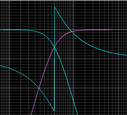
The cause of this destructive (cancellation) and constructive (addition) interference is that multiple sources in different locations are radiating in the same frequency region. At crossover (1 kHz) all three devices are active.
The largest separation of sources is between the horn and the bottom woofer, with a distance of 26 inches. This is almost exactly two wavelengths at 1 kHz.
The distance between the horn and the top woofer is 13 inches, as is the distance between the two woofers. This is almost exactly one wavelength at 1 kHz. This is why there is such good summation above and below (+90 degrees and -90 degrees) the loudspeaker.
The spacing of 13 inches between the woofers is the cause of the decrease in output above and below the loudspeaker at 500 Hz. This distance is almost exactly one-half wavelength at this frequency.
To minimize these directivity problems we need to minimize the interference. This means attenuating a source so that only one is active within a given frequency region.
We can do this with the woofers by placing another low-pass filter on the bottom woofer (in addition to the existing 1 kHz low-pass filter used for the crossover).
We’ll use a second-order Butterworth low-pass filter at 300 Hz to roll off the higher frequency output of the bottom woofer.

The effect of this on the vertical directivity is shown in Figure 7.
The two off-axis cancellations (depressions) around 1 kHz are due to the crossover in this region between the top woofer and horn. The only way to eliminate these cancellations is to eliminate the spacing between the top woofer and horn.
That is to say they would have to occupy to the same point in space, which is clearly not possible. Arranging them co-axially would not eliminate the cancellations, but it would change the angles at which they occur.
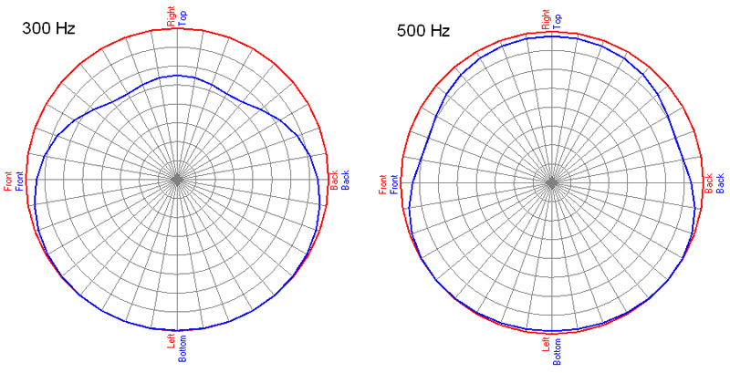
We also see something very peculiar. In the 155-500 Hz region the directivity map is not symmetrical. There is a large region of cancellation above the loudspeaker.

This is also shown in the polar plots of Figure 8. Notice the output is greater below the loudspeaker than it is on-axis.
Some of you may be thinking, “No big deal, I want more output directed down towards the audience from flown loudspeakers anyway.”
This is true, which is why flown or elevated loudspeakers are usually tilted downward and aimed at the audience. The “downward lobe” remains pointing along the vertical axis of the enclosure. When tilted down, this axis is usually pointing towards the stage area.
Starting to see the problem?
How many line array cabinets are on the market with dual woofers or midrange drivers placed on opposites sides of the enclosure?
These same directivity problems will also plague these line array cabinets, but because the drivers are offset horizontally they will occur in the horizontal plane, not the vertical.
