
Condenser microphones need phantom power to operate their internal circuitry.
Phantom power is supplied to the mic through its 2-conductor shielded cable. The power can be supplied either from a stand-alone device or from a mixing console (at each mic connector).
The microphone receives power from, and sends audio to, the mixer along the same cable conductors. It’s called “phantom” because the power does not need a separate cable; it’s “hiding” in the signal conductors.
According to DIN standard 45596, phantom powering is a positive voltage (12-48V DC) on XLR pins 2 and 3 with respect to pin 1. The cable shield is the supply return. There is no voltage between pins 2 and 3. Pin 1 is ground; pin 2 is audio in-polarity, and pin 3 is audio opposite-polarity.

Also, pin 1 has 0 volts; pin 2 has a positive voltage, and pin 3 has the same positive voltage as pin 2. The phantom on/off switch in many consoles is labeled “P48” to signify “phantom power 48 volts.”
Figure 1, top, shows a microphone plugged into a stand-alone phantom power supply. Inside the phantom supply (Figure 1, middle) are two equal resistors R. They supply equal voltage to pins 2 and 3 with respect to the pin 1 ground. Inside the mic, phantom power is tapped off two equal resistors (or a center-tapped transformer).
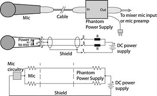
Figure 1, bottom, shows how the phantom current travels through the mic cable from right to left:
1. The current leaves the DC power-supply positive terminal and goes through two equal resistors.
2. The current travels along the mic cable to the mic.
3. The current is recovered inside the mic and goes through the mic circuitry.
4. The current returns to the DC power-supply negative terminal via the cable shield.
Some microphones or mic capsules work on DC bias rather than phantom power. A separate wire supplies B+ to the mic capsule. You’ll see this arrangement in lavalier mics or choir mics between the mic capsule and its XLR connector. The mic capsule itself runs off DC bias, while the XLR connector houses a circuit that runs off phantom power. That circuit converts phantom power to DC bias for the mic capsule, and balances the signal.
Why Condenser Mics Need Powering
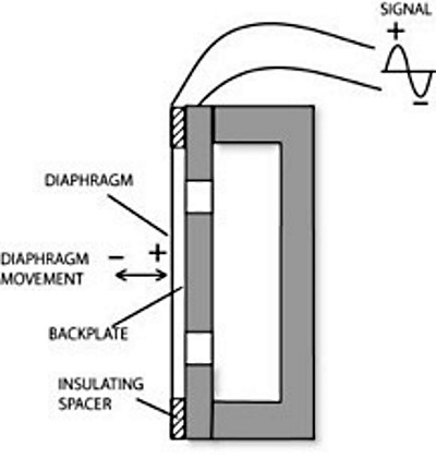
Let’s explain why condenser mics need power in order to operate. In a condenser microphone transducer (Figure 2), a conductive diaphragm and an adjacent metallic disk (backplate) are charged with static electricity to form two plates of a capacitor.
When sound waves strike the diaphragm, they vary the spacing between the plates. This varies the capacitance and generates an electrical signal similar to the incoming sound wave.
The diaphragm and backplate can be charged in two ways:
1. By an externally applied voltage (from phantom power). This arrangement is called “external bias” or “true condenser.”
2. By a permanently charged electret material in the diaphragm or on the backplate. This is called “internal bias” or “electret condenser.”