In part 1, we covered what voltage is and a bit on how it’s measured. Here let’s look at how to use a basic digital voltmeter to measure any power outlet or extension cord for proper voltage.
The reason this procedure is so important is that sometimes venues do crazy things with power outlets. For instance. I was teaching a seminar a while back in a “gymnatorium” and plugged in my little demo rack along with my RF headset receiver.
As I was getting ready to flip the switch on the Furman rack distro, I noticed the built-in voltmeter was pegged to the right of the 120 volt scale. Luckily, I didn’t go further and did not flip on the switch that powered the full rack.
But unluckily for my RF receiver, it was ahead of the Furman power switch so it was already “on” and burning quite brightly for a few seconds. A quick meter test on the power outlet confirmed it had been rigged for 240 volts, even though it was a standard NEMA-5 “Edison” outlet, which should always be wired for 120 volts.
The janitor told me that was his “special outlet” they had rewired for his 240-volt [floor] buffer. But it should have had a 240-volt plug and outlet, not an Edison outlet modified for 240 volts. My bad for not checking.
My RF receiver was toast. Live and learn….
Shake & Bake
Remember when you were a child and first started to help with cooking, and there were all sorts of measuring devices and abbreviations to take into consideration?
There was a tablespoon (Tbsp), teaspoon (tsp), ounce (oz.), with 8 oz. in a cup, and so on. And you better not get your tsp and Tbsp mixed up or bad things would happen to your cake.
The same types of rules apply when you’re measuring any electrical values. You just need to know how to use a few electrical measuring tools and then you’re ready to test your stage power.
The Meter
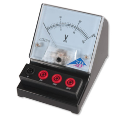
At right we see a pretty typical voltmeter that can be purchased at Lowes, Home Depot or Amazon. You’ll notice a bunch of strange markings on the selection knob, only a few of which will work to measure AC voltage.

Don’t be tempted to just plug the meter leads into a wall outlet and spin the knob. That will guarantee a burned out meter (at the least). Note the markings on the control knob are divided up into four major groups.
• AC V (AC voltage)
• DC A (DC amperage)
• OHM (electrical resistance)
• DC V (DC voltage)
The only two groups you’ll be interested in for measuring voltage are AC V (for measuring the AC voltage in power outlets) and DC V (for measuring the DC voltage in your batteries).
For this article we’ll focus on the AC V group since we’re measuring the 120 or 240 volts AC in a wall outlet or stage power distro.
Also take a look at where the meter leads are plugged into the lower right-hand connections. The Black COM (common) input is always connected to your black meter lead, and the red V Ohm mA (milliamperes) input is always connected to your red meter lead.
Never put either meter lead into the 10A socket, which is designed specifically to check current flow. Doing so will blow the internal fuse in the meter, and possibly damage the meter itself.
All meters read the difference between the two lead connections, so if the black lead is touching 0 volts and the red lead is touching 120 volts, the meter will read 120 volts.
However, if both the red and black leads are touching 120 volts, the meter will indicate 0 volts, which is because 120 minus 120 equals 0.
See how it works?
That’s the key to using a meter. It must be connected between the two voltages you want to measure.
Now, let’s move back to the meter settings. In the AC V area you’ll see a 200 and a 750 setting. When set to 200 the meter will read up to 200 volts, when set to 750 the meter will read up to 750 volts.
Since we could be reading as much as 250 volts in a standard electrical outlet, we’ll always just set this to 750 and leave it alone during all testing. If you set it to 200 and connect it to a 240 outlet, the display will probably stick on 200 Volts and start blinking.
That doesn’t hurt anything in the meter, but it doesn’t tell you the actual voltage. Many meters of this type have a 400- or 600-volt setting, so setting for 400 or 600 volts is fine as well, just as long as it’s set for something more than 250 volts.
And if you have an auto-ranging meter, just set it to read AC volts and it will figure out the proper scale for you.
The Outlet
Let’s start on a common 120-volt, 20-amp outlet like you might find in your living room or on any American stage. At right is what one looks like, and the connections as standardized by the National Electrical Code (NEC).

You’ll see a little U-shaped hole: that is the ground; a taller slot on the left, which is the neutral; and a shorter slot on the right, which is the hot connection.
Don’t be confused if the receptacle is mounted upside down with the ground connection to the top. The taller slot is always the neutral, and the shorter slot is always the hot.
This is a GFCI (Ground Fault Circuit Interrupt) receptacle so there are test and reset buttons. More on this later, but pushing the “test” button should cause the “reset” button to pop out and kill the power from the outlet. Pushing the “reset” button in until you feel a click will restore power to the outlet.
The job of the GFCI is to kill the power to the plug before it kills you, say from a hot chassis condition on your guitar amp.