While it’s nothing new to place a limiter immediately in front of a power amplifier to keep it from clipping, there is more that can be accomplished with a limiter to squeeze a bit more low-frequency performance out of a loudspeaker while keeping it within its safe operating area.
Most loudspeaker systems have a limited excursion capability.
The voice coil and cone assembly can travel only so far before the motor strength significantly decreases, the suspension (surround and/or spider) reaches its limits or both.
This excursion limit is generally known as Xmax. With knowledge of the Xmax of a given driver and the displacement response of this driver in a given enclosure it is possible use a limiter to provide protection from over excursion.
Most low frequency loudspeaker designs have increasing displacement with decreasing frequency.
This keeps the SPL output reasonably flat down to the cut-off frequency of the system. Below the cut-off frequency the SPL decreases while the displacement continues to increase.
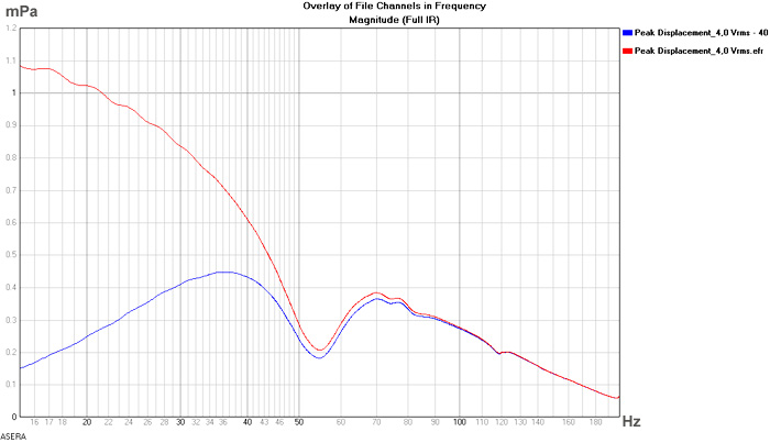
In Figure 1 (below) we see the displacement response for a 15-inch loudspeaker driver in a vented enclosure.
The y-axis is labeled in mPa (millipascals) but the units are really mm (millimeters). EASERA displayed the RMS value of signals so the measurement data have been multiplied by 1.414 so that the display will correspond to the peak displacement of the cone as a function of frequency.
This measurement was made with an input of 4.0 Vrms (5.66 Vpeak). The dip in the curve at 54 Hz is due to the vented enclosure.
In the frequency region of vent tuning the displacement of the driver decreases and will reach a minimum at vent resonance.
For a linear system the displacement response will be directly proportional to the input voltage. This means that the displacement curve can be scaled up or down on the Y-axis as the input voltage is increase or decreased.
For example, we can see that at 100 Hz the displacement is 0.28 mm with an input of 5.66 Vpeak. If the input is 11.31 Vpeak the displacement at 100 Hz will be 0.56 mm.

Doubling the voltage doubles the displacement. At relatively high input voltage the system may no longer remain linear due to power compression (voicecoil heating) as well as excursion limitations (both motor and suspension limits).
The former is a thermal issue related solely to the RMS voltage of the input signal. The latter is related to the peak voltage of the input signal.
Hopefully the program input signal to the loudspeaker system during normal use has a sufficiently high crest factor that Vrms and Vpeak are separated by at least a factor of four (12 dB). The measurements detailed here use a swept sine with a crest factor of 1.414 (3 dB).


