I do this also because I like my neighbors, I think they like me (although I may be delusional) and I would like things to stay this way (I think).
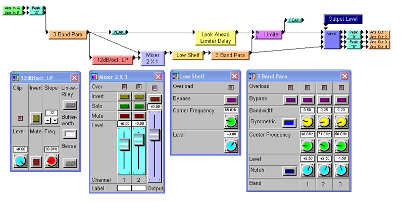
So instead I will test at 4.0 Vrms (5.66 Vpeak) and scale the displacement as if it was tested at the higher voltage. To accomplish this all I need to do is adjust the threshold of the limiter so that it limits at 5.66 Vpeak.
This should be done either with the side chain filtering bypassed or at a frequency much higher than would be affected by these filters.
Because we’re now using a limiter, the system under test is no longer linear, time invariant (LTI).
For this reason FFT measurement techniques, such as those in EASERA and other similar measurement systems, can no longer be used to accurately measure this system. Instead, a steady state sine wave at a fixed frequency is used. The results are recorded and plotted in an Excel spreadsheet.

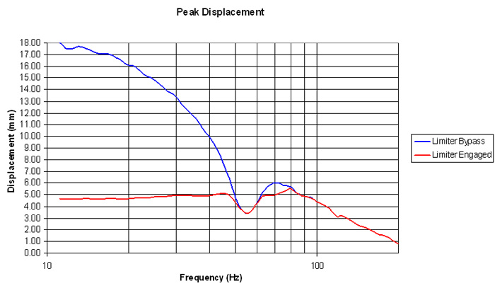
Measurement points for different frequencies are at 1/12 octave spacing. The results are shown in Figure 6.
Here we can see that with the limiter bypassed the displacement is almost identical to that shown in Figure 3.
This is expected. With the limiter engaged the displacement does not exceed 5.0 mm except for a small region around 80 Hz.
This is due to the filters feeding the limiter side chain not being an exact match to the displacement curve in this frequency region. This can also be seen in Figure 4.
One of the additional benefits of this type of low frequency excursion limiting, as opposed to a high pass filter, is that boost EQ can be applied at low frequencies if desired.

At lower signal levels this EQ may subjectively improve the sound of some loudspeaker systems.
The limiter we have implemented will reduce this EQ boost when the signal level is sufficiently high that it would cause the amp to clip or the driver displacement to exceed its recommended range.
In essence, this limiter will remove the EQ momentarily, only at the very highest signal levels containing low frequency energy, and then return the EQ when these high level peaks have decreased below the threshold.
When implemented correctly, this can be very transparent and yield good results.
Many thanks must go to Ray Rayburn, formerly with Peak Audio and currently with K2 Audio, for his valuable insight and patient discussions with a very green engineer many, many years ago on this topic.
Charlie Hughes has worked at Peavey Electronics and Altec Lansing. He currently heads up Excelsior Audio Design & Services; a consultation, design and measurement services company based near Charlotte, NC. Charlie is a member of the AES, ASA, CEA and NSCA. He is an active member of several AES and CEA standards committees.
