A More Simple Method
Ultra Sound has allowed the publication of a simple circuit which when constructed can be used with a microphone and an oscilloscope to measure polarity, phase of a wave, and ringing. Figure 2 is the schematic of an “impulse” generator with variable frequency and repetition rate.
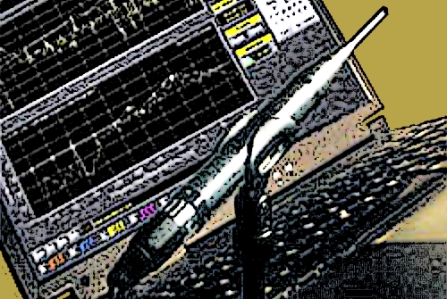
Figure 3 illustrates the proper hook-up of the system. Any oscilloscope with an external trigger will do as will any conventional microphone. Ultra Sound prefers a Nakamichi CM 300 fitted with a CP 3 super-omni s-inch element.

The microphone should be placed a few feet from the loudspeaker (the larger the loudspeaker, the greater the distance between the mic and speaker). The loudspeaker’s impulse output should be loud enough to mask any room noise.

Before testing can be done, the polarity of the microphone to be used as the standard must be determined.
First connect the output arriving at the loudspeaker to the input of the scope and observe whether the waveform is positive or negative going (Figure 4).
Reconnect the loudspeaker to the amp and connect the microphone to the oscilloscope and again observe the polarity.
While observing the scope, adjust it’s trigger from the generator so that the screen shows the waveform that first arrives at the microphone and not a later reflection. At the lowest frequencies, it is possible for the first reflection to look very much like the impulse (Figure 5).
Once the relative polarity.of the test set-up has been determined and the trigger properly adjusted, testing can begin. Whether the test set-up is positive or negative is not important as long as all the adjustments result in the pulse going in the same direction. With the generator putting out a mid-frequency pulse, Figure 6 shows the type of results expected from a 5-inch full-range loudspeaker.

The erratic waves after the pulse are reflections from the room where the tests were made.
As mentioned, the frequency response (Figure 7) will not change regardless of the polarity in a single loudspeaker system.
Figure 8 is the impulse measurement of two 5-inch loudspeakers with identical polarity. Figure 9 is the response of the pair.

Figure 10 has the polarity of the two loudspeakers opposite one another. Figure 11 is the resulting frequency response.
Figure 12 is an overlay of Figure 9 and Figure 11. The efficiency of the two curves was maintained so that a direct comparison could be made. The top trace is of the loudspeakers with identical polarity. The bottom trace has them opposite.

Now that the basic procedure and how to read the impulse is understood, let’s take a look at a two-way system.
Adjust the frequency control of the generator to a low frequency and observe the polarity of the bass loudspeaker. Re-adjust the frequency on the generator to the crossover frequency and observe the polarity of the woofer and tweeter (Figure 13). The small first peak is the tweeter and the second larger one is the woofer.
Both are in the same polarity. Figure 14 shows the response. Figure 15 is the same system but with the tweeter polarity opposite that of the woofer.

Figure 16 is the resulting response showing a substantial dip at the crossover frequency.
Figure 17 again shows a comparison between the system in phase and out of phase response.

The same procedure can be followed with three- and four-way systems. The frequency of the generator is changed to each of the crossover frequencies until the polarity of all the transducers has been determined. If there is more than one driver in any one band range it will be necessary to move the microphone close (one inch) to each driver to eliminate interference from the other drivers in that range. The effect of band-to-band polarity considerations will result in either a peak or a notch in the frequency response at those crossover points.
Another use of the impulse is to check the polarity of microphones. Once the polarity of the test microphone has been determined, other microphones can be compared to it by connecting each microphone in turn to the oscilloscope. If any of the mics are out of phase with the majority, then reverse the signal wires on that mic’s connector.
Currently residing in Australia, Tom Lubin is an internationally recognized music producer and engineer, and is a Lifetime Member of the National Academy of Recording Arts and Sciences (Grammy voting member). He also co-founded the San Francisco chapter of NARAS. The late, legendary Dr. Don Pearson spent more than 25 years on the road providing live sound for literally thousands of shows with Ultra Sound, the sound company he co-founded with Howard Danchik in 1978, and he also contributed numerous reference articles about audio concepts and technology.