
Editor’s Note: This article originally appeared in the late 1980s in Recording Engineer/Producer (RE/P) magazine. Many of the graphics are less than optimum, but we hope they still lend further understanding to the concepts being discussed.
——————————————
When the earliest recordings were done there was little if any attention given to the acoustic phase or electrical polarity of the mechanical devices used to record and reproduce sound.
Phase and polarity have little significance as long as only one microphone picks up the sound and one loudspeaker plays. When recording left the experimental stage it became possible to mix together more than one microphone. This allowed for better control and balance among the instruments.
With advancements in technology, multi-microphone techniques developed. In not too long of a time the recording engineer discovered that occasionally when the outputs of two microphones were combined their summed output level would be less than the output of each one separately. In some cases the cancellation was almost complete and affected all frequencies. In other instances cancellation occurred at certain frequencies only.
Thus, electrical polarity and acoustic phase cancellation became observable problems with the increased use of multi-microphone techniques.
Similar problems existed when monophonic reproduction became stereo. The electrical phase relationship between the two loudspeakers had to be the same.
Multi-loudspeaker systems have made the problem of polarity and phase even more critical as each element must be connected correctly. This may not necessarily mean that the electrical polarity be the same for all of the loudspeakers.
Acoustic phase cancellation occurs in multi-loudspeaker systems as well, but not until very recently had it been acknowledged, possibly because it is less distinct than the cancellation which occurs when two or more microphones that are picking up the same sound are electrically combined.
When our ears mix the signal from two or more loudspeakers what we hear is influenced by the acoustics of the room, and the fact is we have ears instead of amplifiers doing the combining. Before describing a technique for evaluating phase, polarity and a number of other aspects of loudspeaker system analysis, an explanation of polarity and phase should be given.
Polarity and phase are relative terms. Polarity refers to the property that physical quantities have of being greater or less than some reference value that we may arbitrarily designate as the point of reference or “zero.” A point on a line may be thought of as being closer to an observer than another point thought of as a reference or farther away than that same reference point. Its position may be described as corresponding to a positive number in one case and to a negative number in another.
A voltage may be thought of as being positive with respect to one reference potential and another voltage may be observed to be negative referenced to that same potential. Both voltages may be either positive or negative when referenced to the potential of the earth which, by the way, may not be resting at zero with respect to the universe.
Phase is a term that is implicitly linked to an ongoing time sequence of two or more series of events as observed relative to some common reference point in time. Events that are considered to be “in phase” are events that have their time sequences of increase and decrease occurring simultaneously.
Events that are said to be “out of phase” occur in such a way that their increasing and decreasing sequences do not occur precisely together. The measure of the difference in phase is always expressed as a time relation, be it in terms of actual seconds, minutes, hours, etc., or as relative time in terms of increments or fractions of complete cycles of events, such as in units of degrees or radians. It is clear that two or more events may be precisely in phase with one another while being of either positive or negative polarity. Phase and polarity are related although one is not precisely identical to the other.
EIectrical Polarity
Electrical polarity in a loudspeaker is defined in terms of whether the loudspeaker condenses or rarifies when it is energized by a positive pulse (Figure 1). Most manufacturers indicate with colored binding posts a difference between the loudspeaker terminals. Unfortunately, inconsistent or incorrect polarity distinction is quite common, partly due to erratic quality control and the fact that some manufacturers wire their elements opposite to other manufacturers.

The polarity of a woofer can be easily determined with a 1-percent volt battery. When the loudspeaker leads touch the battery terminal, the cone will move in or out. If it moves out the terminal touching the positive side of the battery is positive in that it condenses the air. If the cone moves in then the terminals are reversed. The negative side of the battery is connected to the positive side of the speaker causing the cone to rarify.
Unfortunately, high-frequency loudspeaker elements cannot be checked in this manner because the diaphragm movement is so slight and is usually difficult to see since it is usually deep inside the horn.
Crossovers
In systems that use a number of full-range loudspeakers the phase should be the same for all units; however, with the use of specialized loudspeakers which reproduce only one area of the audio range, a crossover of some type must be introduced into the audio path. Almost all crossovers introduce some degree of phase shift in order to achieve a sufficiently steep roll off to both sides of the pass band.
For example, let’s say we have a three-way network that crosses at 500 Hz and 2,000 Hz. At 500 Hz both the woofer and the mid-range are reproducing a signal that is 3 dB down from their respective full power passband levels.
At that frequency both of them are theoretically reproducing an equal acoustic power level, so their on-axis response will sum by 3 dB. If they sum by 3 dB, and they are both down by 3 dB at the crossover point then the system should have a flat response providing all the phases are correct. But what is the correct phase? That’s the crunch.
The degree of phase rotation introduced by the crossover will vary from unit-to-unit, but can be considerable. Almost always the phase of the roll-off/roll-on of adjacent bands will rotate in opposite directions at the crossover frequency. The net result will have the mid-range acoustically out of phase with the woofer at the crossover frequency because of the phase shift in the crossover.
In order for the entire system to be acoustically in phase at the crossover point, it may be necessary to alternate the loudspeaker polarity of each adjacent band. Manufacturers of crossovers fail to meet this need as phase reversal switches are seldom provided. The fact that the loudspeakers of two adjacent passbands are electrically out of phase is of no consequence since it is only at the crossover points that they share common information, and must be acoustically in phase with one another.
Finally, a loudspeaker is theoretically a single point source of sound. With the addition of each loudspeaker to a system, number of point sources increases. If each point source is not exactly the same distance from the listener then what occurs is an auditory double image. This is particularly apparent at the crossover points.
Basically, a single moment in time is generated by all the loudspeakers at the same instant, but arrives at the listener at a number of different times. This causes the intelligibility of the entire system to be lowered.
Clarity is also affected by “out of band” distortion generated by the enclosure.
If a cabinet is not adequately braced it will resonate or “ring” substantially. The box can put out almost as much sound as the loudspeaker itself.
Likewise metal horns, if not properly dampened, can contribute undesired vibrations.
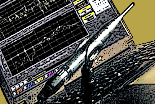
The solution to many of these problems is fairly simple once an accurate method of measurement is provided. Operating as an independent testing service, Don Pearson and Gary Leo, of Ultra Sound, located in Larkspur, California, have developed such a system.
With the aid of their computer they provide information on all of the previously mentioned problems as well as a number of other acoustic and electronic parameters relating to the sound equipment used by their clients.
A permanent record is kept, in the form of a printout, for these clients who number several very prominent sound reinforcement companies.