
Compression drivers and the horns that comprise the horn loudspeaker system have been a part of the audio industry from the very beginning of product development in sound reinforcement systems.
As is true for cone loudspeakers, most of the early development in horn loudspeakers began when sound was first put to picture back in the 1930s when the first “talking films” were released.
Since that time, compression driver technology coupled with horn development advances have been in the areas of materials science allowing improvements in power handling capacity, lower distortion levels, and improvement of directional characteristics of the horn devices.
The chief difference in output when cone loudspeakers are compared with horn loudspeakers is the relative efficiency of the system.
Cone loudspeakers are known as direct radiators due to the fact that they are an electromechanical moving system that couples via the cone directly to the air around it. A great deal of power is needed to move that cone and thereby move the air around it, so it is not very efficient system.
Low efficiency in this case means that with every 100 watts of input power, a cone loudspeaker may only produce 2 or 3 watts of acoustical power output. In comparison, a horn loudspeaker with a midrange compression driver efficiency of 25 to 30 percent will require as little as 10 or 12 watts of power input to produce the same 2 or 3 watts of acoustical power output – a vast improvement in efficiency.
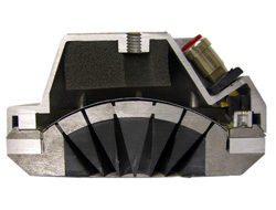
Details of a high-frequency compression driver are shown in Figure 1. The driver consists of a thin diaphragm which is placed about 0.02 inch (0.5 mm) from the phasing plug.

The voice coil at the edge of the diaphragm is immersed in a strong magnetic field. The spherical surface of the phasing plug has a series of annular (circular) slits that extend through the body of the driver to the driver’s exit.
The total area of the slits at the diaphragm side of the driver is approximately one-eighth to one-tenth of the area of the diaphragm itself. It is the area difference which creates the so-called loading factor of the driver, enabling the impedance of the moving system to be properly matched to the impedance of the throat of the horn.