The driver is optimized to produce very high pressures with wide bandwidth at its exit.
Diaphragm materials include aluminum, titanium, and beryllium for drivers with extended frequency response. Phenolic resin impregnated linen materials are used for those drivers intended for limited bandwidth, high power applications.
The phase plug also acts to equalize the path lengths from the surface of the diaphragm to the output of the driver.
In this function it promotes extended high-frequency response by minimizing destructive interferences at high frequencies.
The driver is attached to the horn (Figure 2), which provides a smooth transition from the small area at the throat to the large area at the mouth. It functions as a continuous acoustical transformation, providing an efficient impedance match with the free-air load seen at the mouth.
Essentially, the horn converts a high-pressure/low-volume-velocity relationship at the throat to a high-volume-velocity/low-pressure relationship at the mouth. Early horn designers always used an exponential profile in their horns, since that guaranteed the best overall loading.

The cut-off frequency establishes the lower frequency limit of horn performance. However, in order to attain the desired degree of low frequency performance, the horn’s mouth must be of sufficient size.
A general rule is that the circumference of the mouth should be at least one wavelength at the cutoff frequency if good loading is to extend down to that frequency.
As an example, a horn designed with a cut-off frequency of 500 Hz should have a mouth circumference of about 2 feet. High-quality compression drivers fall into two general categories:
Diaphragm Diameter————————Continuous Power Rating
1-inch to 2-inch small format—————-25 watts to 50 watts
3-inch to 4-inch large format—————-75 watts to 100 watts
These values are approximate and represent a norm in the industry, in general, for a given output level on a given horn, the larger the diameter of the diaphragm the lower the distortion will be. The small format drivers normally have a 1-inch (25-mm) exit diameter, the 3-inch (76-mm) drivers and the 4-inch (100-mm) drivers normally have 1.5-inch (38-mm) or 2-inch (50-mm) exit diameters.
In the real world of loudspeaker specification for professional activities, there is no substitute for actual measurements of drivers mounted on their intended horns. The standard today is to state the mid-band sensitivity of the horn-driver combination, with a power input of one watt and the measurement made at a distance of one meter.
This discussion is excerpted from JBL Audio Engineering For Sound Reinforcement by John Eargle and Chris Foreman. It is distributed by Hal Leonard Publishing.
A Bit More About Drivers…
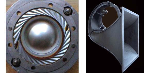
The Western Electric we555 compression driver pictured below (left) looks fairly modern, no?
Believe it or not, however, this unit was introduced in 1928, and enjoyed a long life, finding primary use with cinema sound systems, which were in their infancy.
Often, the we555 was used with the Western Electric 15B horn pictured below (right), and with a low-frequency loudspeaker, was positioned behind the screen – the same as is done today.
Many think the sound quality of the we555 still hasn’t been topped. It initially had a maximum power handling specification of 5 watts, which went up a bit over the years as new versions were introduced. The diaphragm also underwent a number of changes.