
In a digital recording system, sound is stored and manipulated as a stream of discrete numbers, each number representing the air pressure at a particular time.
The numbers are generated by a microphone connected to a circuit called an analog to digital converter, or ADC. Each number is called a sample, and the number of samples taken per second is the sample rate.
Ultimately, the numbers will be converted back into sound by a digital to analog converter, or DAC, connected to a loudspeaker.
Figure 1 (below) shows the components of a digital system.
Notice that the output of the ADC and the input of the DAC consists of a bundle of wires. These wires carry the numbers that are the result of the analog to digital conversion.
The numbers are in the binary number system in which only two characters are used, 1 and 0. (The circuitry is actually built around switches which are either on or off.)

The value of a character depends on its place in the number, just as in the familiar decimal system. Here are a few equivalents:
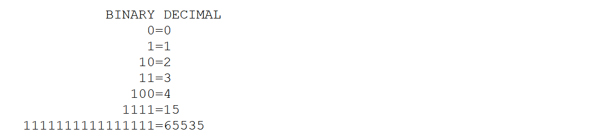
Each digit in a number is called a bit, so that last number is 16 bits long in its binary form. If we wrote the second number as 0000000000000001, it would be sixteen bits long and have a value of 1.
Word Size
The number of bits in the number has a direct bearing on the fidelity of the signal. Figure 2 illustrates how this works. The number of possible voltage levels at the output is simply the number of values that may be represented by the largest possible number (no “in between” values are allowed).

If there were only one bit in the number, the ultimate output would be a pulse wave with a fixed amplitude and more or less the frequency of the input signal. If there are more bits in the number the waveform is more accurately traced, because each added bit doubles the number of possible values.
The distortion is roughly the percentage that the least significant bit represents out of the average value. Distortion in digital systems increases as signal levels decrease, which is the opposite of the behavior of analog systems.
The number of bits in the number also determines the dynamic range. Moving a binary number one space to the left multiplies the value by two (just as moving a decimal number one space to the left multiplies the value by 10), so each bit doubles the voltage that may be represented.
Doubling the voltage increases the power available by 6 dB, so we can see the dynamic range available is about the number of bits times 6 dB.
Sample Rate
The rate at which the numbers are generated is even more important than the number of bits used. Figure 3 illustrates this.

If the sampling rate is lower than the frequency we are trying to capture, entire cycles will be missed, and the decoded result would be too low in frequency and might not resemble the proper waveform at all.
This kind of mistake is called aliasing. If the sampling rate were exactly the frequency of the input, the result would be a straight line, because the same spot on the waveform would be measured each time. This can happen even if the sampling rate is twice the frequency of the input if the input is a sine or similar waveform.
The sampling rate must be greater than twice the frequency measured for accurate results. (The mathematical statement of this is the Nyquist Theorem.) This implies that if we are dealing with sound, we should sample at least 40,000 times per second.
The Nyquist rate (twice the frequency of interest) is the lowest allowable sampling rate. For best results, sampling rates twice or four times this should be used. Figure 4 shows how the waveform improves as the sampling rate is increased.

Even at high sample rates, the output of the system is a series of steps. A Fourier analysis of this would show that everything belonging in the signal would be there along with a healthy dose of the sampling rate and its harmonics.
The extra junk must be removed with a low pass filter that cuts off a little higher than the highest desired frequency. (An identical filter should be placed before the ADC to prevent aliasing of any unsuspected ultrasonic content, such as radio frequency interference.)
If the sampling rate is only twice the frequency of interest, the filters must have a very steep characteristic to allow proper frequency response and satisfactorily reject the sampling clock. Such filters are difficult and expensive to build.
Many systems now use a very high sample rate at the output in order to simplify the filters. The extra samples needed to produce a super high rate are interpolated from the recorded samples.
By the way, the circuits that generate the sample rate must be exceedingly accurate. Any difference between the sample rate used for recording and the rate used at playback will change the pitch of the music, just like an off speed analog tape. Also, any unsteadiness or jitter in the sample clock will distort the signal as it is being converted from or to analog form.