The time window length is a function of frequency, with even the longest window (highest frequency resolution) excluding much of the late energy from the room.
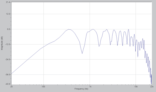
Another caveat of this type of analysis is that much greater frequency detail is possible than with the typical 1/3-octave banded display. Phase interference effects from reflections or multiple drivers are clearly visible on the analyzer.
Such anomalies are almost always position-dependent, so careful “corrections” at one seating position will be inappropriate for another.
Both the loudspeaker and the measurement microphone should be carefully positioned to avoid the creation of very early high-level reflections.
Special Effects?
The “floor bounce” effect is a common example of a very early reflection (typically within a few milliseconds of the first sound arrival) that produces a unique acoustic response for each listener seat for all but the lowest octaves of the spectrum. This is an example of “less is better” when measuring the response, as a 1/3-octave display lacks the resolution to observe the effect in detail and produces less of a temptation to “fix” it.
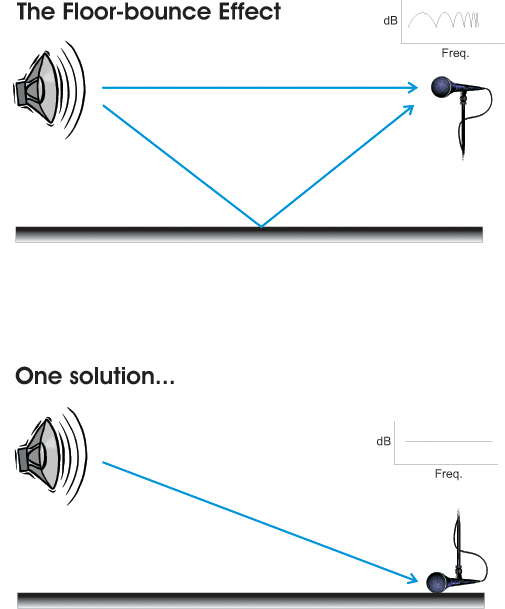
The floor bounce effect can be minimized by use of an appropriate frequency-dependent time window or by simply laying the measurement microphone on the floor, or on a board placed across the listener seats. The effect usually disappears with the presence of an audience, so we do not wish to consider it when tuning the sound system.
The use of variable-length time windows and the synchronous transfer function allow the system to be tuned in a manner similar to the near-field RTA method (flat response on a log frequency display), even at remote positions in the room.
It is superior to the RTA method in that the effects of air absorption are readily apparent and can be compensated for via equalization. Near-field techniques do not include air absorption for the simple fact that the sound has not traveled very far before it is picked up by the microphone, so it hasn’t passed though enough air to be significantly attenuated.
By far, the biggest problem with tuning sound systems is failure on the part of the technician to recognize anomalies that cannot be corrected with equalization.
The equalizer is a “global” device, meaning that its response curve will be impressed on all of the sound radiated from the loudspeaker, regardless of the direction in which it is radiated.
Many, if not most, of the anomalies observed on the analyzer are unique to each listener position. The technician must learn to recognize and ignore such events. They include:
—Floor-bounce effect
—Interference between multiple drivers
—Reflections from objects near the mic or loudspeaker
Events that produce a more global effect, and can therefore be addressed with equalization include:
—Boundary-loading of loudspeakers
—Coupling between multiple low-frequency drivers
—The direct-field loudspeaker response
With training and experience, the system technician can implement methods that reveal system imperfections that are correctable, and hide those that are not – regardless of the analysis method used. Better yet, system designers can design systems with fewer “un-equalizable” problems.
Bad Is Always Bad