
In a previous article (“Loudspeaker Sensitivity”), I examined the topic of loudspeaker sensitivity and how it may or may not relate to the overall sound pressure level (SPL) produced by a loudspeaker.
One of the conclusions of that article is that the SPL produced will be dependent on the spectral content of the signal driving the loudspeaker. Thus, having knowledge of the driving signal (i.e., program material) or being able to make an educated assumption about it may aid in the design of a loudspeaker or sound reinforcement system so that the required bandwidth and SPL is delivered to the audience.
The output capability of the amplifier driving the loudspeaker is of equal importance to achieving the target SPL from the direct field of a loudspeaker. This can also be related to the driving signal or the intended program material.
Pat Brown authored a very interesting and enlightening article (“Loudspeaker Toaster,” SynAudCon Newsletter, Winter 2006) on testing loudspeakers to determine what I refer to as their maximum usable continuous output SPL.
While a loudspeaker may be capable of producing greater continuous SPL, it is accompanied by significant changes (greater than 3 dB) in the transfer function (frequency response) of the loudspeaker. For most applications this is undesirable and thus deemed not usable.
This “toaster test” primarily focuses on the thermal effects the input signal has on the loudspeaker system; the individual driver’s voice coils, the resultant impedance increase, and the passive crossover components (if present).
The result of the toaster test yields a maximum RMS voltage (max Vrms) that can be applied to the loudspeaker without driving it past this Maximum Usable Continuous Output SPL (SPLMUCO). This max Vrms may then be used to calculate an Equivalent Amplifier Size, which can deliver the max Vrms when driven by this same test signal.
This signal, by the way, is specified by the standard IEC 60268. It is a broadband, shaped noise signal with a spectral content that is the average of a variety of program material, including both speech and several different types of music. This test signal has a crest factor of 6 dB.
To get the most out of the rest of the article we need to understand crest factor so let’s briefly explain it:
—The crest factor of a signal is simply the difference between the RMS level and the peak level of the signal.
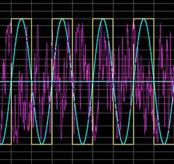
—A square wave has a crest factor of 0 dB; it has the same RMS level as its peak level.
—A sine wave has a crest factor is 3 dB, that is its RMS level is 3 dB less than its peak level.
For more complex waveforms the crest factor may be different, and is usually higher. Many waveform editing programs have analysis capabilities that will calculate the RMS and peak levels of an entire .wav file or a selected segment.
In Figure 1 we see 100 ms segments of a 100 Hz square wave, a 100 Hz sine wave, and IEC60268 noise. All of the signals shown here have been normalized to have a peak level of 0 dB.

Now that we understand crest factor, we can use the results of the toaster test performed on a particular loudspeaker to help determine the required amplifier size for our sound reinforcement system design.
Differences between the spectral content of our program material and that of the signal used for the toaster test to determine max Vrms may lead to inaccuracies in our results. However, as long as these spectral differences are not dramatic, the results should be reasonably valid.