Boundary Loading
Loudspeaker-boundary interference response is an interaction between a loudspeaker’s direct sound and the adjacent boundaries. This mostly affects low frequency as they’re usually omnidirectional. It can be useful or create unwanted comb filtering.
The lower the frequency, the bigger the wavelength is. Since the sound’s wavelength can be greater than 3 m and loudspeakers’ dimensions are usually less than 2 m, a loudspeaker is usually spreading low frequencies like a sphere, or omnidirectionally (projecting sound to all direction with equal energy).
This omnidirectional characteristic is valid if a subwoofer is hung far from boundaries. Once a loudspeaker is placed on a reflective floor, the radiation becomes hemispherical because the floor reflects half of the sound energy.
By putting a subwoofer on the floor (half space), in the corner of two walls (quarter space), or two walls and floor/ceiling (eighth space), the subwoofers gain extra output. One boundary can add up to 6 dB output, especially for low frequencies.
Half Space
To understand how a loudspeaker interacts with a boundary, we will discuss how sound behaves in a half space mounting condition, assuming the wall is reflective. A common half space condition is flush mounted loudspeaker where the body of the loudspeaker is inside the wall as shown in Figure 11 (left side).
In a flush-mounted condition (assuming the loudspeaker is properly designed for this – no drivers/ports at the side/back), sound waves spread via the front only. At frequencies where the loudspeaker directivity is low (usually less than 500 Hz), the output will rise.
Flush mounted condition is usually done at one corner of the room, so aside from the low frequency rise, room modes are excited more. At high frequencies, the flush mount condition may not affect the frequency response output if done properly.
Figure 11 (right side) shows a common loudspeaker placement, which is in a front of a wall. By placing the loudspeaker at a certain distance from the wall to the front of the loudspeaker, a cancellation occurs at frequency with 1/4-wavelength of the distance. If the front of loudspeaker is approximately 60 cm away from the wall, a notch in frequency response can be noticed at ±143 Hz.
While the flush-mount condition seems ideal (because it gives extra low-frequency output and extends the low-frequency response of the loudspeaker), it’s not very practical for most situations.
Putting loudspeakers in the front of a wall is typically used. The closer the loudspeaker is to a wall (less than 1 m), the higher the frequency cancellation will be. This higher frequency cancellation/comb filter may not be too noticeable and thick absorbers behind a loudspeaker can be used to control this.
The extra low-frequency output (boundary loading) may be desirable, and few loudspeaker manufactures provide low-shelf filter to reduce the effect. When the distance between loudspeaker and the wall is greater than 1 m, comb filtering starts at low/low-mid frequencies. This can create subjective impression such as hollow or thin sound, and boundary interference is harder (or more expensive) to control.
Lastly, putting a subwoofer or loudspeaker on the floor is also a half space condition. The output rise depends on the listener position and the directivity of the loudspeaker. Figure 12 shows a point source radiation of a loudspeaker. Point source means it radiates from one point of origin (another type of source is line source).
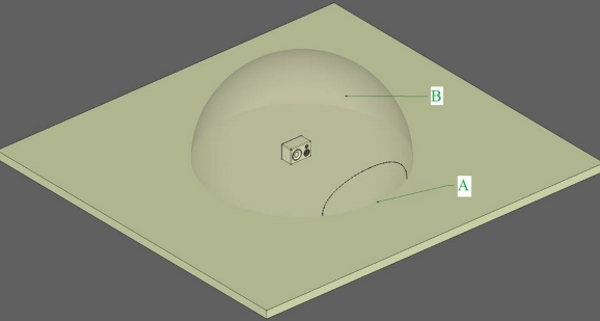
When you place the same loudspeaker on a floor (assuming the boundary is solid, reflective and smooth), the radiation becomes a hemisphere as shown in Figure 13.
In both Figures 12 and 13, an ellipse is shown in the front of the loudspeaker. This illustrates the focused radiation of mid/high frequency and the main sphere illustrates the low-frequency radiation. The focused radiation/directivity of the loudspeaker is usually noted by its -6 dB downpoint.
In this example, the ellipse shows the location where mid/high frequencies are down 6 dB relative to the loudspeaker’s on-axis reference point (center of the ellipse). Outside the location of the ellipse, the attenuation of mid/high frequencies are greater than 6 dB.
In Figure 13, two locations are noted as A and B. Location A is in the front of the loudspeaker, right on the ground. This location will receive +6 dB gain at all frequencies due to the boundary/floor.
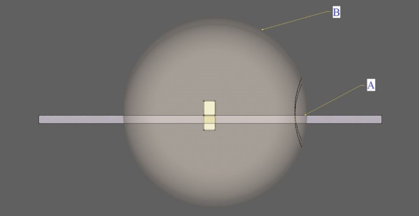
At location B, the low frequencies will likely receive +6 dB gain but it is outside of the loudspeaker’s mid/high main radiation/sound lobes. This will result in little or no output gain, as well as the possibility of comb filtering in the mid/high frequency response. Figure 14 shows the side view of Figure 13.
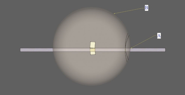
The boundary acts like an imaginary mirror for sound waves. In Figure 14, the top loudspeaker is the loudspeaker, and the bottom loudspeaker is the sound source’s mirror image. Note: the radiation sphere from each sound source are misaligned at location B, but aligned at location A.
Due to the slight path difference in location B, this can cause comb filtering as previously discussed and the extra overall gain caused by the boundary is less than 6 dB (closer to 3 dB in general).
A common method of loudspeaker’s measurement is called ground plane measurement. By tilting the loudspeaker a little bit and locating the microphone at location A in Figure 15, one is able to measure frequency response without getting destructive interfering reflections from floor.
This can also be applied to microphone placement for recording purposes such as capturing a guitar/bass/keyboard amp.
Visualizing Point Source Propagation
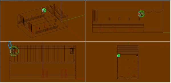
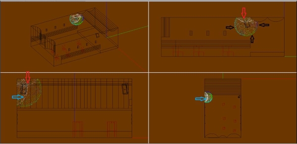
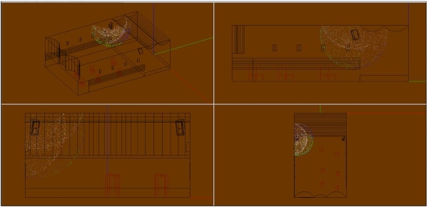
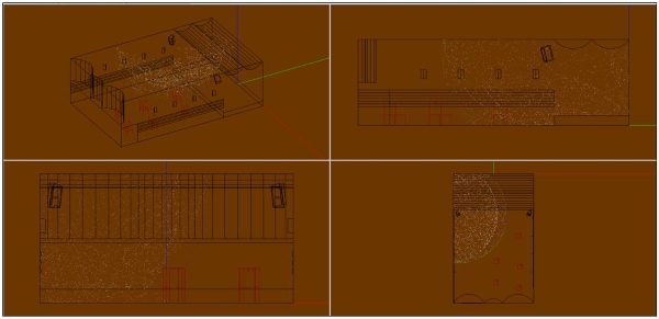
Several pictures below shows sound propagation of one loudspeaker installed in a medium hall with dimensions of 14.5 m x 9 m x 4.6 m.
The loudspeaker used is a 2-way with 15-inch direct radiating woofer and 60- x 60-degree horns on the high frequencies. Four snapshots of sound propagation at 2 ms, 4 ms, 8 ms and 16 ms are shown.
At 2 ms, shown in Figure 16, sound starts to propagate like a sphere. The light blue arrow shows the first reflection from the closest side wall. As noted previously, this boundary interference will boost low frequency output (less than 200 Hz) and create comb filtering at mid frequencies (200 – 2000 Hz).
It likely has less/no influence at high frequencies (greater than 2000 Hz) due to the focused radiation of the 60- x 60-degree horn.
At 4 ms (Figure 17), we can tell that direct sound (noted by black arrows) are leading and will arrive first. You may notice that the black arrows point to different colors. This shows the focused radiation of the loudspeaker to the front (light blue particles), less radiation to the bottom of loudspeaker (green particles) and much less radiation to the back of loudspeaker (blue particles).
Light blue arrows show the side wall reflection and red arrows show the second reflection from the ceiling above the loudspeakers.
At 8 ms (Figure 18) and 16 ms (Figure 19), you can further observe the sound propagation as it expands and fills the room. This medium directivity loudspeaker will project most sound to the audience area, while providing less spill of mid/high frequencies to the stage.
Electronic Correction
Electronic correction in a form of equalization (EQ) can be used to lower the peak/bump in frequency response due to room effect. However, it cannot fix cancellation/notches.
It is also known to create equalization based on energy average of several measurement points in the room, also known as spatial averages. This is done because frequency responses are different at various locations in a room. Spatial average does not have phase information, therefore it is typical to use FIR linear phase filter to flatten or shape the spatial average curve in a room so the loudspeaker’s phase response is not affected by the filter’s phase. Custom FIR filter can be created using software such as Filter Hose.
EQ does not substitute acoustical treatments in small or large rooms, but it can help to smooth out acoustical distortions.
Conclusion
Understanding how a room and loudspeaker interacts is the key to answering why a loudspeaker sounds different when moved to another room. By knowing the problems, correct acoustical treatments can be prescribed to achieve the needed acoustical function.
Hadi Sumoro and Xian Yu are principals of HX Audio Lab, providing acoustic/audio consultation for almost a decade. The authors would like to thank Chris Devenney, Pat Brown (www.ProSoundTraining.com) and Neil Shade (Acoustical Design Collaborative) for their insights and for reviewing this article prior to publication.
You can find a PDF of this article here.


