

When it comes to mixing consoles, the digital revolution has firmly and forever changed the way we approach live sound, especially touring engineers. One of the key features is the ability to totally recall all the console settings from a previous show which enables us to evolve a mix over time rather than build it from scratch every day.
However, if you’re not in the fortunate position of being able to travel with your own console or specify the same model at every show, then you’ll probably end up using a varying assortment of house consoles from different manufacturers and soon discover that this great feature isn’t always available to you.
The problem is that there’s currently no way to transfer a show file from the console of one manufacturer to another; you might even struggle to transfer a file between consoles from the same manufacturer (especially if you’re working with older hardware or software). It means you can quickly go from using a mature show file one day to having to build your mix from scratch the next.
But why isn’t it possible to transfer show files between manufacturers? A show file is just a bunch of numbers – numbers that represent the state of all the controls on a console as well as all the signal routing, effects, snapshots and parameters which comprise the modern mix – so surely it should be relatively straight forward to translate all these values between different consoles? This is the challenge I have set myself as I attempt to create: The Universal Show File.
Low-Tech Approach
Before you get too excited, this isn’t going to be some kind of clever computer program that effortlessly translates the settings of one manufacturer’s console to another. In fact, it’s a slightly more low-tech approach in the form of a spreadsheet.
Those who are old enough to remember analog console recall sheets will recognize the core of the same idea here. The key difference is that rather than recalling the settings to the same console, we’ll be recording the settings in such a way as to enable them to be translated to any other console (even an analog one).
So, let’s start by taking a look at the range of digital consoles currently available. The “big six” manufacturers I come across on a regular basis are Allen & Heath, Avid, DiGiCo, Midas, Soundcraft, and Yamaha. Additional manufacturers include Behringer, Mackie, PreSonus, QSC, Roland and TASCAM, and in my travels I’ve also come across consoles from CADAC, Innovason, Lawo, SSL and Studer, so straightaway we have at least 17 different systems to navigate.
However, for the sake of simplicity (and my sanity) I’ll be referring to the big six whenever I say “all consoles” – but the principles discussed should easily translate to any console.
Clarifying The Process
Before we start, there are a few caveats we need to establish in order to clarify the process we are about to undertake. The aim isn’t to slavishly record the exact values as they appear on the source console or show file. We’re going to be translating all the pertinent values to a universal format which should more easily enable them to be transcribed to a different console.
Therefore, it’s important that we distinguish between the values that are absolute and those that are relative. Absolute values are those that will always be the same on different consoles whereas relative ones are defined by their context and will require a degree of translation. For example, a delay or the ratio setting on a compressor will always be absolute while an input gain or gate threshold are more likely to be relative.
We’ll also be avoiding any features that are unique to a specific console or manufacturer. This includes various types of “analog warmth” and tube emulation as well as supplementary equalization and sidechain functionality. If it doesn’t exist on all consoles then it isn’t universal and thus is beyond the scope of this project.
The reason we’re using a spreadsheet to represent all the values is because it enables us to place the data into columns representing individual channels and rows detailing each parameter. This is organized in a logical sequence, from the microphone preamp at the top to the fader at the bottom, to represent a familiar channel strip that should enable us to make better sense of what is going to be a large grid of numbers.
Getting Started
Let’s start at the top of the channel with the preamp and our old friend the input gain. If we look at the “big six” manufacturers, the gain range available can be anything from 50 to 80 decibels between various negative and positive values, which isn’t easy to translate. We could be really clever and figure out the gain in terms of the electrical voltage (i.e., dBv or dBu values), but this information can be difficult to find (trust me I’ve tried) so I’m going to fall back on an old trick I used on analog consoles – use the corresponding clock face values.
So, all we have to do is note the clock face value that corresponds to the position of the rotary control as if it were the hour hand – using half past and quarter past where necessary to get a suitably accurate value – so in the example provided in Figure 1, we would type it in as 11.30. This may seem like an oversimplification, but you might be surprised just how consistent the gain settings are when referenced this way.

In addition, there are so many variables involved in the input level of a signal from show to show that an approximate value is acceptable because it will always be the first thing you check during the line check.
The next control we encounter is the digital trim, and it’s best to record this as an absolute value in decibels because it’s a modifier and thus should be consistent. If the console doesn’t have digital trim then just leave the value blank.
Next we have the three “p” switches: pad, polarity and phantom power, which can be recorded as being either on or off. Purists might argue that the pad can be a variable value between different models but on every console I was able to check, it’s always -20 dB. So, if you come across one that’s different just record the attenuation value and adjust the gain accordingly when recalling to a console with a different pad.
The final stage of the preamp is the high- and low-pass filters. All consoles have a high-pass but not all have a low-pass, so record the relevant values as an absolute number in Hertz. Some high-pass filters also have a variable slope so it’s worth recording this value (in dB per octave) if it’s present. Figure 2 offers an example with the pre-amp values filled out for a simple 16 channel set-up comprising drums, bass, two guitars, a stereo keyboard and three vocals.
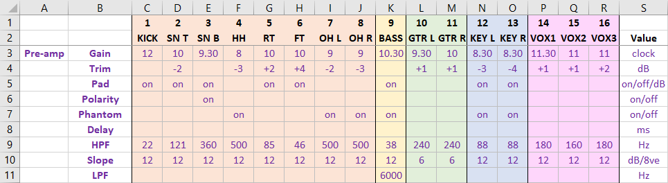
To make it easier to distinguish specific values in the sea of numbers, I’ve used cell shading to differentiate different channel type, i.e., orange for drums, yellow for bass, green for guitars, blue for keys and pink for vocals. These are the same colors I use for those channel types on the console itself, which should help make storage and recall easier. I’ll also be using different colors for the text of each horizontal section of the console.
You’ll see that I’ve added a “value” column to the end that denotes what each value represents, be they clock face measurements, an on/off switch, decibels, milliseconds or hertz (and I’ve kept all frequency values in Hertz to avoid any confusion between Hertz and kiloHertz). I also decided it’s best not to enter a value where there is none or it’s set to default (such as 0 dB for the trim or “off” for the switches) in order to avoid clutter and the risk of false recall due to number blindness.
Equalization
Up next is the EQ section, which all consoles divide up into four separate filters: high, high-mid, low-mid and low, all of which typically have the three common parameters of gain, frequency and bandwidth. The high and low filters often include the ability to switch between shelf and bell filters, so we need to include that information, which means our EQ section will appear as shown in Figure 3.
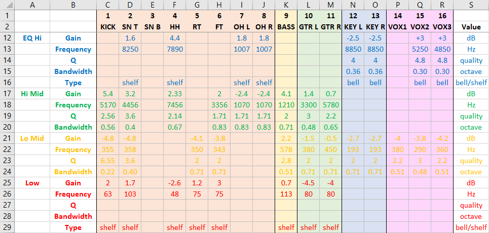
I’ve locked the top two rows of the spreadsheet so that as I scroll down, the column headers will always stay visible. While EQ algorithms will inevitably differ from console to console, I’m going to assume that all values for gain and frequency are absolute and just write them down as is, which just leaves the bandwidth.
Most consoles define the width of the EQ filter in terms of its quality, or Q, but some define it as bandwidth (represented in octaves or fractions thereof), while others offer the ability to switch between these two units or select the appropriate unit, depending on which EQ algorithm has been selected.
Because Q represents the ratio of the center frequency to the difference in the higher and lower frequencies, which are cut or boosted by a lesser degree (i.e., 3 dB), a wide filter has a low value (e.g., 0.1) and a narrow filter has a high value (e.g., 10). Meanwhile, bandwidth (in octaves) gives values that are inversely proportional. This can make translating such values tricky, so to save time and much head scratching, I’ve come up with this simple conversion chart (Figure 4).
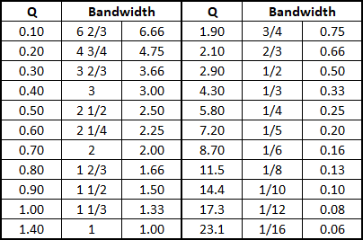
So, all we need do is find the value in either Q or bandwidth and select the corresponding value (I’ve listed the bandwidth octave figures as both fractions and decimals). If you want a more accurate figure but don’t want to do the math, just search online for “bandwidth to q conversion calculator.” Look at the EQ diagram again and you’ll see that I’ve already converted the Q values from the source console to bandwidth, so I have both values available when I recall them to the target console.
Sends
Channel sends are pretty straightforward. Monitor sends are typically pre fader while effects sends are usually post fader. While some consoles enable individual sends on individual channels to be switchable, I’m going to assume that the whole bus is either pre or post fader and use slightly different colors to differentiate them.
In the example provided in Figure 5, there are four pre fade monitor sends for the drummer, guitar/keyboard player, center vocalist and bassist, as well as two reverbs and two delays. Again, I only enter a value for sends that are in use or enabled, so any blank values denote that the send is at its lowest setting or off (which equates to the same thing).
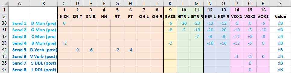
Because the values are anchored around the nominal level of 0 dB, they can be treated as absolute and just written down as they are. Obviously the monitor outputs will go directly to stage wedges or in-ear monitors and the effects sends will go to the effect units (be they internal or external).
It makes sense to include details of the effects because they’re a key part of the overall mix, but effects parameters can differ greatly from console to console, making it difficult to find a universal system to store them. Therefore, it’s pointless to copy the exact effects parameters because they simply won’t translate so we’ll just extract the core parameters that define the general nature of the effect to a separate tab in the main spreadsheet (Figure 6).
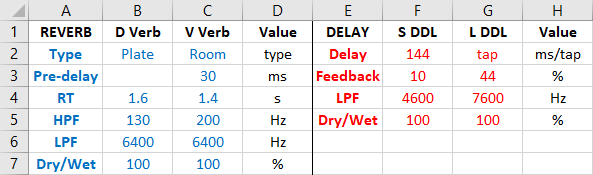
So, for the reverbs I have selected the reverb type, pre-delay, reverb time, high-pass filter, low-pass filter and the dry/wet balance, and for the delays I’ve selected the delay time (either in milliseconds or dictated by a tap button), the feedback percentage, low-pass filter and dry/wet balance.
Dynamics
Before we get to the bottom of our channel, we need to think about any in-line dynamic processing such as gates and compressors. I’m aware that many consoles include other dynamics processor (i.e., de-essers and expanders) but they typically have the same controls so the values can easily be entered in the same format (Figure 7).
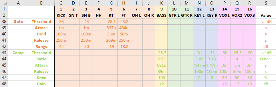
If we start with the gate threshold setting, we instantly hit a snag due to the fact that not all consoles agree where zero is – while most cover a range of about 80 dB, some go from -60 to +20 dB while others go from -80 to 0 dB. The simple solution I’ve come up with is to look at the maximum value for the threshold setting on the source console and subtract that from the actual threshold value.
For example, if the console’s maximum gate threshold value is +20 and the threshold is set to -6, log -26 for the value, whereas if the maximum value is 0 and the threshold is set to -26, log it as -26. This has the effect of recalibrating all the values such that they’re all negative relative to the maximum value of 0 dB, which makes it easier to translate the value to the target console.
The next three controls we have are attack, hold and release, all of which are absolute time values and so can be recorded as they are (in seconds). Some consoles employ values in micro and milliseconds, so I’ve used the standard notation of “u” and “m” to identify micro and milli accordingly.
For the gate, we have range. Some consoles call it depth, but it’s the same as range insofar as it defines the amount of attenuation applied to the signal once the gate closes. There’s some variation between consoles in terms of the range, but they all go from zero to maximum attenuation (i.e., completely off). Some class it as amplification and give it a negative value, whereas others define it as attenuation so they give it a positive value. At the end of the day, it’s a relatively mundane semantic argument that I’ll avoid by entering it as a negative value and then just switch the sign accordingly on storage or recall.
With the compressor we can use the same trick for the threshold of subtracting the maximum value from the actual value to get a universal negative value. The ratio, attack, release and gain values are all absolute and nicely universal so can just be entered as is.
That just leaves the knee, and again we confront the issue that there’s no commonly used method for representing this value – some use a percentage while others offer a switch between soft/medium/hard or just a series of numbers to represent the degree of knee. Therefore, I think the best way to ensure ease of translation is to store the value as a percentage where 0 is hard and 100 is soft, and in situations where there are only hard/medium/soft options just log it as 0, 50 or 100, respectively.
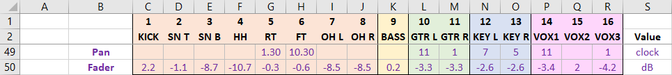
We can now complete our journey down the input channel with the last two controls, the pan and fader. For the pan, we can use the same trick as the gain and use the clock face to record the values, while the fader value is an absolute value relative to nominal zero (Figure 8).
Recall
In order to recall the settings to a target console, all we need do is reverse the process detailed above. Thanks to the prevalence of offline editing software we don’t even need to be at the console to recall The Universal Show File, which makes it something we can easily do in advance.
Please bear in mind that while the example used in this article is based on an actual show file of mine, I’ve tweaked some of the values in order to provide a wide range of examples of the values you might come across so I can’t promise it will sound particularly good if you try to run a band through it.
Conclusion
I started this article with the suggestion that show files are just a bunch of numbers that should easily lend themselves to the process of translation from one console to another, but along the way I started to realize that it’s a bit more complex than that. Attempting to copy a show file in this fashion is always going to be an approximation – it’s not simply a process of translation but rather one of interpretation – none of the values are truly absolute because each console interprets them slightly differently.
This doesn’t mean the process is of no use. An approximation of an existing show file is always going to be better than building one from scratch, so giving ourselves a head start and getting some of the basic values copied across leaves more time for the all-important finessing of the mix. That alone has to be worth a little time and effort.


