Previously I have explored the theoretical aspects of balanced interfaces and de-bunked the widespread myth that equal and opposite signal swings are somehow responsible for its noise-rejection properties.
In this column, we will explain how to find most problems that degrade performance in real-world systems.
The problems fall into two broad categories.
The first is design errors in the equipment itself, most often the “Pin 1 problem” that couples shield current noise into the audio.
The second is problems caused by the type and/or routing of the audio cables themselves.
Since cable shields are tied to Pin 1 in XLR connections, this equipment design error was dubbed the “Pin 1 problem” by Neil Muncy in his famous 1995 AES Journal paper. This form of common-impedance coupling has been inadvertently designed into a surprising number of well-known products with balanced interfaces.
As Neil says, “Balancing is thus acquiring a tarnished reputation, which it does not deserve. This is indeed a curious situation. Balanced line-level interconnections are supposed to ensure noisefree system performance, but often they do not.” (1)
The Pin 1 problem makes the cable shield contact act as a very low-impedance signal input! Shield current, consisting mainly of power-line noise, is allowed to flow in internal wiring or circuit board traces shared by amplifier circuitry. Because these wires or traces have electrical resistance, tiny voltage drops are created and amplified to appear at the equipment output.
When this problem exists in systems, it can interact with other noise coupling mechanisms to make noise problems seem illogical and confounding. This problem can afflict video and other unbalanced interfaces, too.
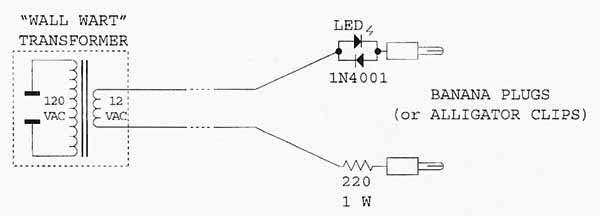
Fortunately, a simple test will reveal the Pin 1 problem. The “hummer” (Figure 1) is based on an idea suggested by John Windt (2). This simple device, whose schematic is shown here, forces an AC current of about 50 mA to flow through the potentially troublesome shield connections in the equipment under test.
In property designed gear, this causes no additional noise at the equipment output. The 12-volt transformer should be rated for about 50 mA. The optional LED (and 1N4001 diode) are used simply to confirm that current is indeed flowing.
Using the hummer, step by step:
1. Except for the output being monitored, disconnect all other cables and any other chassis connections, such as rack mounting, from the equipment under test.
2. Power up the equipment.
3. Meter (and listen to, if possible) its output. The only noise should be white noise or “hiss.” Try various settings of operator controls to familiarize yourself with the noise characteristics of the device under test without the hummer connected.
4. Connect one hummer lead to the device chassis and touch the other lead to the shield contact of each input or output connector. If the device is properly designed, there will be no output hum or change in the noise floor.
5. Test other potentially troublesome paths, such as from an input shield contact to an output shield contact or from the safety ground Pin of the power cord to the chassis or shield contacts. No such path should result in noise.


