Rarely, shield contacts are not tied directly to chassis or safety ground and the hummer’s LED will not glow.
This is cause for concern, especially on an output—output shields must always be grounded (3).
In any case, try to find out where the manufacturer has actually tied the shield connection.
Easily constructed test adapters or “dummies” allow the system to test itself and pinpoint the exact entry point of noise or interference.
By temporarily placing the dummies at strategic locations in the interface, precise information about the nature of the problem is also revealed.
The tests can specifically identify:
• Shield-current-induced coupling in cables
• Magnetic or electrostatic pickup by cables of nearby fields, or
• Common-impedance coupling inside defective equipment
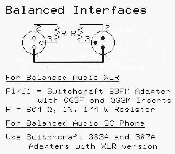
The dummies are made from standard connectors wired as shown in Figure 2—do not connect the metal shell to Pin 1. Remember that they do not pass signal.
Each signal interface is tested using the following four-step procedure:
Step 1
Unplug the existing cable from the input of Box B and plug in only the dummy.
Output quiet?
No—The problem is either in Box B or further downstream.
Yes—Go to next step.
Step 2
Leaving the dummy in place at the input of Box B, plug the existing cable into the dummy.
Output quiet?
No—Box B has an internal “Pin 1 problem.” The hummer test can confirm this.
Yes—Go to next step.
Step 3
Remove the dummy and plug the existing cable into the input of Box B. Unplug the other end of the cable from Box A and plug it into the dummy. Be sure the dummy doesn’t touch anything conductive.
Output quiet?
No—Noise is being induced in the cable by an external magnetic or electric field. Check cable shield connections at both ends and/or re-route the cable to avoid interfering fields.
Yes—Go to next step.
Step 4
Leaving the dummy in place on the existing cable, plug the dummy into the output of Box A.
Output quiet?
No—The problem is shield-current-induced noise or SCIN. Replace the cable with a different type or take steps to reduce current flow in the shield (4).
Yes—The noise must be coming from the output of Box A. Perform this 4-step test sequence at the next upstream interface.
Bill Whitlock has served as president of Jensen Transformers for more than 20 years and is recognized as one of the foremost technical writers in professional audio.
REFERNECES
(1) Muncy, N., Noise Susceptibility in Analog and Digital Signal Processing Systems, Journal of the Audio Engineering Society, June 1995, pp. 435-453.
(2) Windt, J., An Easily Implemented Procedure for Identifying Potential Electromagnetic Compatibility Problems in New Equipment and Existing Systems: The Hummer Test, Journal of the Audio Engineering Society, June 1995, pp. 484-487.
(3) Whitlock, B., Balanced Lines in Audio Systems: Fact, Fiction, and Transformers, Journal of the Audio Engineering Society, June 1995, pp. 460-462.
(4) Brown, ]. and Whitlock, B., Common-Mode to Differential-Mode Conversion in Shielded Twisted-Pair Cables (Shield Current-Induced Noise), Preprint 5747, Audio Engineering Society 114th Convention, March 2003, Amsterdam


