
Finite Impulse Response (FIR) filters (pronounced either “F-I-R” or alternately, like the tree) are the rage these days.Like many things in audio, they have been around a very long time, but technology has now evolved to allow their practical implementation. Is this the panacea that we have been waiting for, the “filter messiah” that will finally allow perfect sound reproduction?
Of course not, but they are pretty cool nonetheless, and they can be a game changer for some applications.
This is part 1 of a series that will examine the use of FIR filters in sound reinforcement systems. There are plenty of textbooks and resources on the Internet that delve into the mathematics and the deep theory. That’s a bottomless well that can never be exhausted.
In this series I’ll use a broad brush stroke to give some “take-aways” on FIR filter theory along with practical implementations and examples. These will hopefully prove beneficial for understanding FIRs and integrating FIR filter technology into your projects.
I will assume an understanding on the part of the reader of basic signal theory, including the time and frequency domains of signal analysis as implemented by modern audio and acoustic analyzers.
What Are They?
One way to understand FIR filters is to consider how they compare to their counterpart, the Infinite Impulse Response (IIR) filter. In general, IIRs are either analog, or they are digital filters that behave like analog filters. IIRs accomplish their response by using feedback (the good kind) to return some of the output signal back to the input for reprocessing. This “recursive” behavior means that in theory the filter’s impulse response (theoretically) never decays to zero. Of course, it does in a practical sense since the output signal eventually diminishes into the noise floor. Given their use of feedback, IIR filters can be unstable if not designed properly. Analog filters are IIR.
Let’s say we use an analog or IIR parametric equalizer to create a loudspeaker equalization curve (Figures 1 and 2). There is a high-pass response, a low-pass response, and some boost and cut filters within the passband.

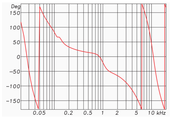
Each “bump” in the response exhibits a phase shift (negative-going phase angle) for those frequencies, and each “dip” exhibits the opposite phase shift (positive-going phase) for those frequencies. Both the high-pass and low-pass responses produce a negative-going phase angle with increasing frequency.
In other words, changes in the magnitude response are accompanied by shifts in the phase response. These phase shifts are unavoidable and inherent to the filter. In fact, they can often be predicted from looking at the magnitude response. When the magnitude and phase response are related in this predictable way, the relationship is called “minimum phase” and it is (sometimes) a desirable property of the filters.
Why? Because the bumps and dips in the loudspeaker’s frequency response are also (usually) minimum phase. This means that the equalizer fully “equalizes” the loudspeaker’s response, resulting in a smoother magnitude and phase response. So, in this context, “phase shift” is not an evil byproduct of using filters, as some might have you believe. As always, “it depends.”
To clarify, “minimum phase” does not mean the absence of phase shift. It means that the phase response exhibits the minimum possible shift for the given magnitude response, and that one can be predicted by the other. May measurement programs can calculate the minimum phase response, given the magnitude response.
Linear Phase
A FIR filter can have changes in its magnitude response that do not produce corresponding shifts in the phase response. Using the previous filter set, I replaced the HP and LP IIR filters with FIR filters of the same magnitude response.
The phase response of such a filter is a straight line vs. frequency (linear frequency axis), so it is termed “linear phase.” Note that the phase shift due to the HP and LP have been removed, leaving only the phase shift produced by the boost and cut filters (Figure 3).

So, for a minimum phase filter the magnitude and phase response are interdependent, and for an FIR filter they can be independent. FIR filters can change the magnitude response without changing the phase response.
For the remainder of this series, I will assume that IIR filters are minimum phase and that FIR filters can be linear phase. If exactly the same magnitude response curve were created with each, the phase responses could be different. In fact, if one looked only at the phase response of the HP and LP FIR filters in my example, they would have no idea that any filtering was going on.
Where FIRs really shine is when used for frequency dividing networks. The high-pass filter (HPF) used to protect a horn driver can be made arbitrarily steep using an FIR. Slopes of 96 dB/octave and higher can be realized.


