Most measurement systems acquire it by playing a log sine sweep, or “chirp” through the system, and capturing and processing the response into the IR.
The IR can be transformed to the frequency domain (Fast Fourier Transform or FFT), and displayed as a magnitude/phase plot. The magnitude/phase plot can be transformed (inverse Fast Fourier transform or iFFT) back to the time domain to be displayed as an impulse. As such, filters behavior can be described in either the time or frequency domains. If you’re using one of the garden variety dual-channel FFT measurement platforms, you’re already familiar with these concepts.
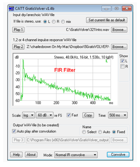
What’s this got to do with FIR filters? Impulse responses of loudspeakers and rooms are FIR filters, since they completely decay to zero (or noise) due to their finite length. Those who use GratisVolver to convolve room impulse responses (RIR) with anechoic program material are already working with FIR filters (Figure 9). For that reason, FIRs are sometimes called “time domain” or “convolution” filters, even though the actual implementation may be via multiplication in the frequency domain, carried out in software or hardware.
The IR of a loudspeaker can be transformed to the frequency domain and displayed as a frequency magnitude and phase. If inverted in the frequency domain (flipped upside-down), it is the exact conjugate (opposite) of the loudspeaker’s response in both magnitude and phase (Figure 10).
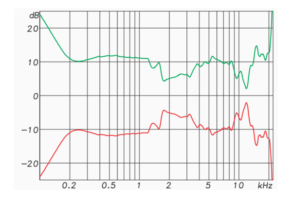
If the original and conjugate response are multiplied, they completely cancel each other, resulting in a flat line for the magnitude and phase (frequency domain) or a perfect impulse in the time domain.
This has tremendous implications for equalization work – any measured response can be used as a filter. FIR “correction” filters can be used to:
1. Make the loudspeaker’s response perfectly flat in magnitude and phase, even compensating for anomalies caused by throat reflections, grill effects and edge diffraction.
2. Make corrections for room anomalies such as boundary effects near a loudspeaker, and (more in theory than practice) room reflections.
3. Improve the response of line arrays by allowing individual processing for each array component. This can allow beam shaping and steering not possible with analog filters.
The FIR can be convolved with program material and used as a filter. While this has been possible for decades, it’s now becoming practical. Many DSPs are adding support for FIR filters, allowing an IR to be convolved in real-time with the program material passing through it.
But before you get too excited about have “perfect” loudspeaker responses, and cancelling room reflections, we have much more to discuss.
“Perfection” becomes possible through FIR filter equalization at a point in space. Since no two points in space have the same IR, we cannot extend the “correction” to an area. That doesn’t mean that FIR equalization is not useful, just that there are “push backs” that keep it from creating the perfect listening experience. We have to settle for some of the benefits under specific conditions that become increasingly difficult to realize as the room size increases.
Conclusion
Here are some take-aways from this introduction to FIR filters:
1. The FIR can change the loudspeaker’s magnitude response without changing its phase response. This can allow very steep crossover filters that don’t introduce phase shift to the response. This linear phase behavior comes at the expense of latency.
2. Any measured impulse response can be used as an FIR filter. This can allow us to listen to room data, such as with GratisVolver, or perform corrective equalization not possible otherwise. It can even be done on the fly, such as the echo cancellation utilized in conference room systems.
3. FIRs can be implemented in software using convolution. An example is the use of GratisVolver to listen to room impulse response.
4. FIRs can be implemented in hardware and used for real-time signal processing. Several DSPs now support user-specified FIR filters.
So, in the sound reinforcement world, FIRs are mostly about:
1. Crossover networks.
2. Corrective equalization for loudspeakers.
3. Listening to room responses via convolution, whether measured or generated by a room modeling program.
4. Beam forming in line array systems.
Audio filters are no longer just a collection of capacitors, inductors and resistors, or the equivalent realized through the use of integrated circuits. They can be produced by measurements or mathematical algorithms, and be implemented in real-time by advanced digital signal processing techniques.
In part 2, I’ll cover some more FIR filter basics, and show a couple of ways to produce “brickwall linear phase” FIR filters for a crossover network, including some measurements on real loudspeakers.