What is phase shift?
Phase shift is a term describing the displacement of two signals in time.
When we described the two sides of a balanced line as being of opposite polarity, we could have said that they are 180 degrees out of phase with each other.
Each time an AC waveform completes a cycle from zero to positive peak to zero to negative peak and back to zero, it travels though 360 degrees (just like a circle).
A simple 1 kHz (1,000 cycles per second) sine wave travels through this 360-degree rotation in one millisecond.
If we consider its starting point to be zero, it will reach its positive peak one-quarter of a millisecond later, cross zero in another one-quarter of a millisecond, reach its negative peak a quarter-millisecond after that, and return to zero after a fourth quarter of a millisecond has elapsed.
Thus, each quarter of a millisecond equals 90 degrees of phase difference. When two identical signals are in phase with one another, their zero crossings and peaks are the same, and summing (combining) the two will double the amplitude of the signal. When they are 180 degrees out of phase, summing them will result in cancellation of both signals.
This property is very straightforward when considering simple sine waves. Sine waves consist only of a single fundamental frequency and have no harmonics. Harmonics are multiples of the fundamental, and are the elements of which complex waveforms are composed.
An excellent example of complex waveforms is called music. The reason a middle C note on a piano sounds different from the same note played on a flute is because the two instruments generate different waveforms – the harmonics of the piano are present in different amounts and have different attack and decay characteristics than the harmonics of the flute.
When complex waveforms are traveling in a cable, it would be ideal if the amplitude and phase relationships they enter the cable with are the same as those they exit the cable with. When the
effects of phase shift alter those relationships – when the upper harmonics that define the initial “pluck” of a string, for instance, are delayed with respect to the fundamental that forms the “body” of the note – a sort of subtle “smearing” begins to occur, and the sense of immediacy and realism of the music is diminished.
How can phase shift be minimized?
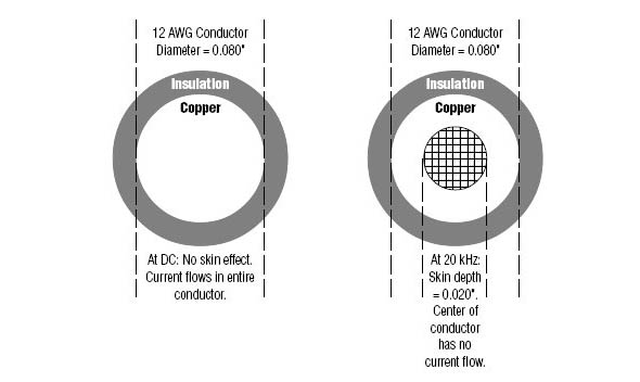
The phase lag caused by skin effect is one radian (about 57.3 degrees) per skin depth, and the effective skin depth of a conductor at a particular frequency is the same whether the conductor is very large or very small in diameter. For instance, the skin depth of a copper wire at 20 kHz is about .020 inches, while an 18 AWG conductor has a diameter of about .040 inches. This means that at frequencies from DC to 20 kHz, the full cross-sectional area of the conductor is utilized.
Because the skin depth (.020 inch) is never less than half the diameter of the conductor (.040 inch), there is never more than one radian of phase shift present. In short, star-quad cables seem to offer lower inductance and lower phase shift, both of which are parameters that directly affect the clarity and coherence of high-frequency complex waveforms.
Their inherently superior noise-rejection also reduces intermodulation distortion, a type which is particularly offensive because it produces “side-tones” not harmonically related to the fundamental. While the improvement may not be as dramatic as changing the microphone, an increasing number of audio professionals seem to be embracing the sonic benefits of star-quad construction.
What about the insulation? Does it affect the sound?
Even though the effects of cable capacitance are much less than that encountered in high-impedance applications, the use of low-loss, high-quality (low dielectric constant) insulation materials such as polyethylene and polypropylene are still preferred, especially when long cable runs are necessary.
Because of the desire to keep cable diameter to approximately 1/4 inch, the insulation thickness of a typical two-conductor microphone cable is generally about .020 inches, half that of a coaxial-type instrument cable. This relatively thin wall means that soldering requires good heat control to prevent melting.
For very thin (.010 inch) applications, cross-linked polyethylene insulation is sometimes used. The cross-linking process (similar to that used in manufacturing heat-shrinkable tubing) greatly reduces the problems of insulation meltdown and shrinkage during soldering.