Why are the two conductors twisted together?
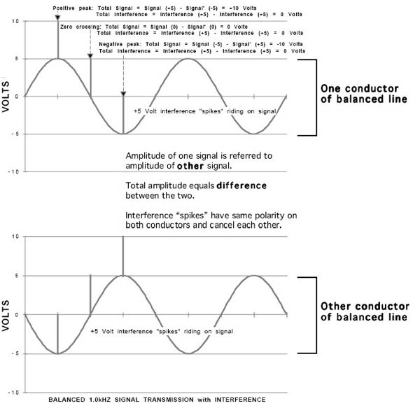
As previously explained, the interference-canceling common-mode rejection of the balanced line is based on the premise that the unwanted external noise is induced into both signal conductors equally.
Minimizing the distance between the two conductors by twisting them together helps to equalize their reception of external interference and improve the common-mode rejection ratio (CMRR) of the line.
The two conductors also form a sort of “loop antenna” for stray magnetic fields. The farther apart the two conductors are the larger the “antenna” becomes, and the more interference it picks up from sources like transformers, fluorescent lighting ballasts, SCR-chopped AC lines to stage lighting, etc.
Minimizing the loop area of the cable helps to reduce the unwanted hum and buzz from this type of interference, which the cable’s shield is almost totally ineffective against.
The distance between the twists is called the lay of the pair. Shortening the lay (increasing the number of twists) improves its common-mode rejection, and also improves its flexibility. The typical pair lay in microphone cables is about 3/4-inch to 1-1/2 inches. Shortening the pair lay uses more wire and more machine time to produce the same overall finished length, so of course it increases the cost of the cable.
What is “star-quad” cable?
This four-conductor-shielded configuration can best be thought of as two twisted pairs twisted together. Using four small conductors in place of two large ones allows the loop area of the cable to be further reduced and its rejection of electromagnetic interference (EMI) is improved by a factor of ten (20 dB). This makes star-quad cable very popular for microphones and balanced lines used in applications such as television production, where huge amounts of power cable for lighting and camera equipment surround the performers.
Does star-quad actually sound better?
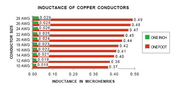
When used for low-impedance microphones, star-quad construction substantially reduces the inductive reactance of the cable. Inductance was previously mentioned in discussing impedance. An inductor can be thought of as a resistor whose resistance increases as frequency increases.
Thus, series inductance has a low-pass filter characteristic, progressively attenuating high frequencies. While parallel capacitance, the enemy of high-frequency response in high-impedance instrument cable, is largely insignificant in low-impedance applications, series inductance (expressed in microHenries, or uH) is not. The inductance of a round conductor is largely independent of its diameter or gauge, and is not directly proportional to its length, either. Parallel inductors behave like parallel resistors: paralleling two inductors of equal value doesn’t double the inductance, it halves it.
In cable construction, using two 25 AWG conductors connected in parallel to replace each of the conductors of a 22 AWG twisted pair will result in the same DC resistance, but approximately half the series inductance. This will result in improved high-frequency performance: better clarity without the need for equalization to boost the high end.
Also of significance is skin effect, a phenomenon that causes current flow in a round conductor to be concentrated more to the surface of the conductor at higher frequencies, almost as if it were a hollow tube. This increases the apparent resistance of the conductor at high frequencies, and also brings significant phase shift.