
What is impedance?
Impedance is the AC (alternating current) version of the DC (direct current) term resistance, which is the opposition to electron current flow in a circuit and is expressed in ohms.
Impedance (often abbreviated as “Z”) includes capactive reactance and inductive reactance in addition to simple DC resistance.
Reactance depends upon the frequency of the signal flowing in the circuit.
Capactive reactance increases as frequency decreases: inductive reactance increases as frequency increases. Because of this frequency dependence, impedance is not directly measurable with a multimeter as DC resistance is.
What are the differences between high- and low-impedance microphones?
To answer this requires a little historical background. High-impedance microphones are capable of producing higher output voltages than low-impedance types. Until recently, “consumer” audio gear (small PA systems, home and semi-pro recording equipment, etc.) was always designed for high-Z mics because their relatively high output level required less amplification or gain.
The lower output of low-Z mics required the equipment manufacturer to use input transformers in front of the mic preamplifiers to step up the strength of the signal, which substantially increased the cost of the circuitry.
Hence, low-Z mics were rare outside of professional recording and broadcast studios. In these “big-budget” facilities, low impedance lines offered several big advantages. A high-Z mic’s high source impedance (approximately 10,000 ohms) combines with the capactive shunt reactance of the mic cable to form a low-pass filter which progressively cuts high frequencies. The severity of the loss is determined primarily by the length and construction of the cable.
The low source impedance (less than 200 ohms) of low-Z microphones proportionally reduces the high-frequency loss. Equally important, the high load impedances demanded by high-Z lines are much more susceptible to various forms of interference than low-Z lines, especially high-frequency noise and radio. Both of these high-Z liabilities made cable runs longer than 15-20 feet a problem.
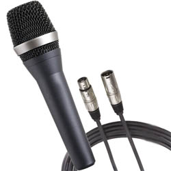
Isn’t the use of balanced lines the biggest advantage of low-impedance microphones? What is a balanced line?
Balanced lines are wonderful, but they are sometimes given credit for benefits that they are not actually responsible for. Balanced, unbalanced, low-impedance and high-impedance are all individual properties.
Many people erroneously refer to anything with a 3-pin XLR-type connector as “low impedance” and assume it to be “balanced.” Others call any line connecting two pieces of equipment with 1/4-inch phone jacks “high-Z.” In reality, a lot of equipment has unbalanced inputs and outputs that are carried on XLR connectors, and there are even more low-Z lines on phone jacks.
Medical instrumentation uses a lot of high-impedance balanced lines for sensors, and most line-level unbalanced outputs are very low-impedance.
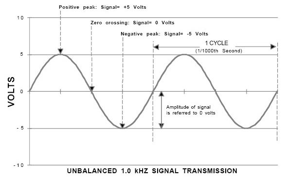
Electrical systems need a reference point for their voltages. Generally referred to as common or ground, although it may not be actually connected with the earth, this reference remains at “zero volts” while the “hot” signal voltage “swings” positive (above) and negative (below) it. This is referred to as an unbalanced configuration.
Physically, the common may be a wire, a trace on a printed-circuit board, a metal chassis – virtually anything that conducts electricity. Ideally it is a perfect conductor – that is, it must have no resistance or impedance. In a cable connecting two pieces of equipment, the shield is used as signal common.
As the complexity and size of the system is increased, the imperfect conductivity of the common (ground) conductor inevitably causes problems. Since it is made of a real material, it must have some resistance, which must (Ohm’s Law says) cause voltage drop when current flows through it, which means it cannot be at a perfect “zero volts” at both ends. The larger the system and the greater the distances between the source and load, the less effective this unbalanced configuration becomes.
The voltages of a balanced line are not referenced to the ground or common. Instead, the signal is carried on a pair of conductors with the signal applied to this pair differentially. The signals are electrical “mirror images” of each other – their levels are the same, but their polarities are opposite.
In other words, as the applied signal “swings,” one conductor will be negative with respect to the common, the other will be positive. These polarities alternate with the frequency of the signal, and the total signal level is the difference between the two individual voltages.
For example, if one conductor is at +5 volts, the other will be at -5 volts, and the signal level is +5 volts minus -5 volts or 10 volts. If, for same reason, the two conductors were both at +5 volts simultaneously, the level would be +5 volts minus +5 volts, which is zero volts. Very tricky!
Because of this differential signal transmission, two very valuable things happen when using balanced lines. First of all, each piece of equipment can have its circuitry referenced to its own common, because the interconnection of the equipment does not require that the commons are connected in order to move the signal around. This eliminates the major cause of a lot of noisy audio gremlins, ground loops.
Secondly, because the signal is differentially transmitted and received, any common-mode interference signal superimposed on the signal in the line will be carried by both sides at identical level and polarity. In other words, if the line has +5 volts of external noise induced, both conductors will have +5 volts of noise on them. This equals a total interference level of +5 volts minus +5 volts or zero volts. The interference cancels itself. This is called common-mode rejection.


