
It seems nothing is ever easy. However simple they might appear, making fixed resistive attenuators (I’ll call them pads in this article) requires doing some math if you want them to come out right.
Sure, you could simply hook up some resistors and see what you get, but that’s not audio engineering.
The reasons for doing the math are simple: to make both the pad and the equipment you are using with the pad work properly.
You will see why you should do the proper engineering when you read the notes that follow here. Excessive noise, excessive loading, potential pad failure, and incorrect results will be avoided.
Instructions
To calculate resistive pads for typical pro audio equipment, follow the formulas in Figure 1 on the next page of this article post (here) to find the values you need. It’s fairly easy as long as you know how to do basic math formulas.
If you’re rusty, remember to calculate things inside parentheses first [e.g. (R1 + R2)]. Use the answer you get to continue the calculation. There are also step-by-step instructions for doing the log/dB calculations on your calculator.
As rough checks for your calculations:
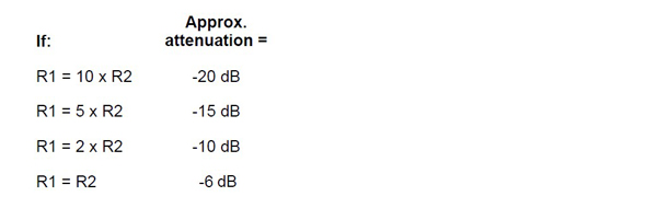
Balanced Vs Unbalanced Pads
If the output equipment or input equipment is unbalanced, use an unbalanced pad. If both are balanced, then use a balanced pad.
Important Notes (and here is where the real engineering comes in)
Avoiding Incorrect Results: Always measure the resistors you will use with an Ohmmeter. Do not accept the nominal values of resistors as accurate. This is especially true for R2. With high amounts of attenuation, variations in R2 will have a more significant effect on the attenuation.
Avoiding Incorrect Results: For certain pieces of equipment you may find when selecting the “R values” that it is not possible to find values that are within the criteria given. This means that you will not have a “constant” voltage circuit.
The consequence is some additional attenuation will take place either from loading down the output (RS) or loading down the output of the pad with input (RL). In this case go for the latter and use an R2 that is greater than (>) RL/10. You must then figure the total resistance of R2 and RL in parallel:

Use this “Total R” as R2 in the equations. It will work just fine.
If you swap out the equipment fed by a pad where R2 > RL/10, then you must either use one with about the same RL (input impedance) or redo the pad to get the same attenuation.
Always maintain R1 + R2 > 10 x RS. The reason for this is to ensure that the resulting circuit allows the driving equipment to operate as the constant voltage device it was designed to be. Loading it down with less than 10 times the output impedance means possible distortion, overheating, or other undesirable consequences.
You Do Not Have the Resistor You Need (Also Avoids Incorrect Results): You can make up odd resistor values by putting two or more in parallel or series. Always measure your combination with an Ohmmeter. Do not accept the nominal values of resistors as accurate.
To calculate what you need for two parallel resistors use this formula. R1 is a known resistor, RT is the total resistance you want to get, and R2 is the resistor you need to put in parallel with R1 to get RT:
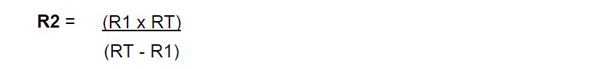
If putting resistors in series, the total resistance is found by simply adding resistor values together. So if you have a 1000 Ohms and you need 1100 Ohms, put a 100-Ohm in series with the 1000 Ohms: 1000 + 100 = 1100.
Avoiding Noise: Low tolerance (1 percent or better) resistors for the R1s are a must to use in balanced pads to help maintain the CMRR (Common Mode Rejection Ratio) of the input stage in the receiving equipment.
In addition, if you have a good Ohmmeter, you should try matching up the two series R1 resistors as close as you can from a batch with the same nominal value.


