Where To Install The Pad (Also Avoids Noise): You should always put pads at the receiving end of the cable so that the cable “sees” the low output impedance (RS) over its length rather than the higher R2. Also the signal level will be higher in the cable. These things will help prevent noise intrusion.
Normally, you can usually squeeze a resistive pad inside an XLR connector. Just be sure to label the cable accordingly. For 1/4-inch plugs you can also put it inside the sleeve, though it’s usually a fussy job.
You can also hard-wire it into the cable near the receiving end or build it into a small utility box with the pad inside and appropriate connectors and/or pigtails with connectors on them. Be sure to connect the cable shield to the box.
Avoiding Pad Failures: When pad attenuates a signal, where does the excess signal you are getting rid of go?
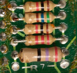
The resistors in the pad dissipate the excess signal as heat. So you need to find out just how much heat (in watts) the resistors in the pad must dissipate. If you don’t, the resistors may overheat and either change value or burn up and stop working. Neither situation is a good thing for a pad.
You can safely use a 1/4-watt resistor for R1 for equipment that can put out +24 dBv/24 dBm or less (about 12 volts in either case) and if R1 is 1,000 Ohms or higher (= two 500-Ohm resistors for a balanced pad).
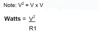
If R1 is less than 1,000 Ohms or your equipment can put out more than +24 dBv, then calculate the wattage R1 needs to be. Use this worst-case formula where “V” is the maximum output of the equipment driving the pad. The formula is worst-case because it assumes a short circuit across the output of the pad. If all you have is a + dB number for the output specification, then you must covert it to volts. This article will tell you how.
Now double this number and that’s the wattage you should use for R1 = twice the expected worst-case condition. It’s best to be conservative. In the case of balanced pads where the resistors values are 1/2 R1, the wattage you calculate is what you should use.
This is because each resistor will only dissipate 1/2 the wattage. For the 1,000 Ohm R1 and a 12 volt (+24 dBv) output capability criteria, the wattage works out to be 0.14 watts. Double it and you need a 1/4-watt resistor for an unbalanced pad or two 1/8-watt resistors for a balanced pad.
If your equipment could put out +28 dBv, the wattage works out to be almost 0.4 watts the resistor would need to be able to dissipate. For a 500-Ohm R1 and +24 dBv it is 0.3 watts. In either case, a 1/4-watt resistor would be too small. It would likely overheat if the equipment was at full output and there was a short circuit across the output of the pad.
You could probably get away with it, but designing for worst-case is part of good engineering. If R1 is 2,000 Ohms or higher, then 1/8-watt resistors can be used for a 12-volt (+24 dBv or dBm) output.
R2 Wattage (Also Avoids Pad Failures and Incorrect Results): You can use a 1/4-watt resistor for R2 if it is 200 Ohms or higher and the driving equipment can put out 12 volts (+24 dB) or less. If R2 is 400 Ohms or higher, you can use 1/8-watt resistors.
To work out the wattage needed for R2, find V2 from the formula in Figure 1 and use this for V in the “Watts” formula. A small change in for R2 will significantly change the attenuation of the pad.
So I’ve been doubly conservative in the R2 wattage requirements using four times the wattage that might be dissipated. Be very conservative in the wattage requirements for R2 to avoid any small changes in value that could occur with heating.

Summary
You should know now that making what would appear to be a simple device using two or three resistors is not that easy. It requires thoughtful engineering design to avoid a number of potential problems.
So get out your calculator and Ohmmeter and get to work. You will have the satisfaction of knowing you did it the right way and that they will work properly and reliably.