This paper discusses the pitfalls (often subtle) of our industry’s failure to define and standardize what “unity gain” means, and the conditions necessary to measure it. It further discusses how people improperly use one piece of misinformation (impedance matching) to correct for this lack of standardization.
All done, without knowing discrepancies exist between different pieces of equipment, and without knowing impedance matching is unnecessary, signal degrading, and wasteful.
For me, it began with a phone call. The caller said he wanted to know our output impedance so he could add the proper load impedance.
“Why would you want to do such a thing?” I asked. “Because I want to maintain unity gain through each piece of signal processing gear,” he replied.
That gave me pause. Then I laughed and realized what he was doing right, and what he was doing wrong. The problem stems from another case of our industry working without proper guidelines and standards. This one involves the conditions used to establish unity gain. Lately, the popular trend of including unity gain detent points and reference marks only aggravates things.
This paper identifies and explains the problem. Once understood, the solution becomes easy—and it doesn’t involve impedance matching.
Unity Does Not Always Equal One
It begins with an understanding of unity gain. Simple enough. Ask anyone and they will tell you unity gain means that if I put, say, 1 volt in, I get 1 volt out, i.e., a gain of one, or unity. Nothing could be easier. That is until that same someone asks the question, “Is that unity gain balanced or unbalanced ?”
Herein lies the problem. Today we find that many (most?) pro audio signal processors have a gain difference of 6 dB between unbalanced and balanced out (exceptions to this are units with output transformers, or cross-coupled output stages). This x2 difference results from differentially driving the line.
Figure 1 shows how an input signal drives one side of the line positively and the other side negatively (each line driving amplifier has a gain of one, but together they yield a gain a two).
For example, a +1 volt peak AC input signal drives one side to +1 volt while simultaneously driving the other side to -1 volt. This gives a balanced output level of +2 volts peak (the difference between +1 volt and -1 volt). Alternatively, that same input signal drives an unbalanced line to +1 volt peak.
Thus, there is a 6 dB disparity between an unbalanced and a balanced output—a gain difference factor of two. Here, unity equals two.
No Standards
This brings us to the part about no standards. Without a standard defining the specified conditions for unity gain, manufacturers make their own decision as to what “unity gain” means.
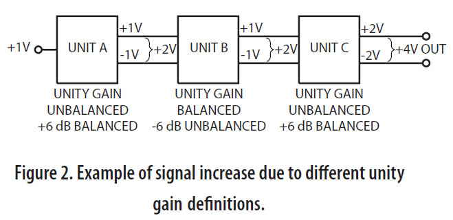
For one, it means 1 volt in gives 1 volt out unbalanced, and 2 volts out balanced. For another, it means 1 volt in gives 1 volt out balanced, and 1/2 volt out unbalanced. For yet others, it means 1 volt in gives 1 volt out (using transformers), or 2 volts out (using cross-coupled stages), either balanced or unbalanced. Very confusing (Figure 2).
Impedance matching went out with vacuum tubes, Edsels and beehive hairdos. Modern transistor and op-amp stages do not require impedance matching. If done, impedance matching degrades audio performance .
Modern solid-state devices transfer voltage between products, not power. Optimum power transfer requires impedance matching. Optimum voltage transfer does not.
Today’s products have high input impedances and low output impedances. These are compatible with each other. Low impedance output stages drive high impedance input stages. This way, there is no loading, or signal loss, between stages. No longer concerned about the transfer of power, today’s low output/high input impedances allow the almost lossless transfer of signal voltages.
What then, does impedance matching have to do with unity gain? Well, it shouldn’t have anything to do with it. But because of different manufacturer’s definitions, it is one way (brute force) of correcting gain discrepancies between products. Impedance matching introduces a 6 dB pad between units . Let’s see how this works.
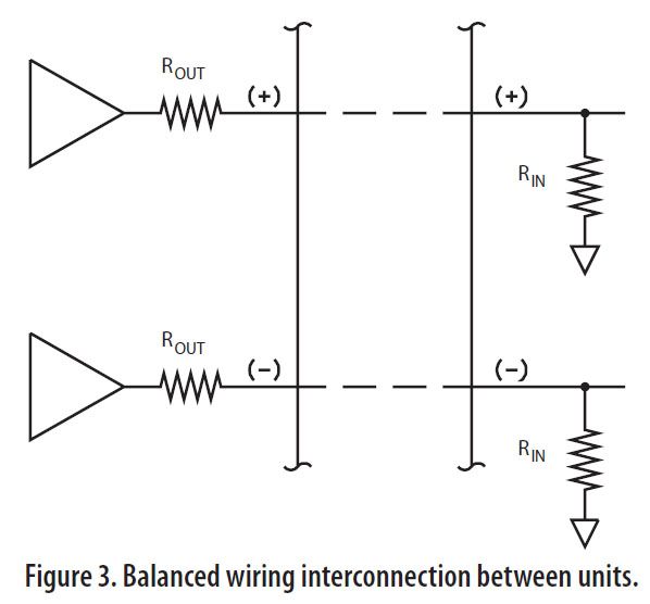
Look at Figure 3. Here we see a real world interface between two units. The positive and negative outputs of the driving unit have an output impedance labeled R OUT. Each input has an impedance labeled R IN. Typically these are around 100 ohms for R OUT and 20k ohms for R IN.
Georg Ohm taught us that 100 ohms driving 20k ohms (looking only at one side for simplicity) creates a voltage divider, but a very small one (-0.04 dB). This illustrates the above point about achieving almost perfect voltage transfer, if impedance matching is not done.
If it is done, you lose half your signal. Here’s how: impedance matching these units involves adding 100 ohm resistors (equal to R OUT ) to each input (paralleling R IN ). The new input impedance now becomes essentially the same as the output impedance (100 ohms in parallel with 20k ohms equals 99.5 ohms), therefore matching. Applying Ohm’s law to this new circuit tells us that 100 ohms driving 100 ohms creates a voltage divider of 1/2.
That is, 1/2 of our signal drops across R OUT and 1/2 drops across R IN , for a voltage loss of 6 dB. We lose half our signal in heat across R OUT . Not a terribly desirable thing to do; yet, it does fix our unity gain problem.
Back to Figure 2. By selectively impedance matching only between Units A and B, we introduce a 6 dB pad. This cancels the 6 dB gain resulting from using balanced outputs with this unit. This changes the output of Unit A to ± 1/2 V, or +1 V balanced.
Since Unit B already is unity gain balanced, then we do not impedance match, and its output is also ± 1/2 V. We do impedance match Unit C’s output and now Unit C passes this +1 V signal to its output as ± 1/2 V, and finally we get a true unity gain result from all three boxes. One volt in, produces one volt out—balanced.


