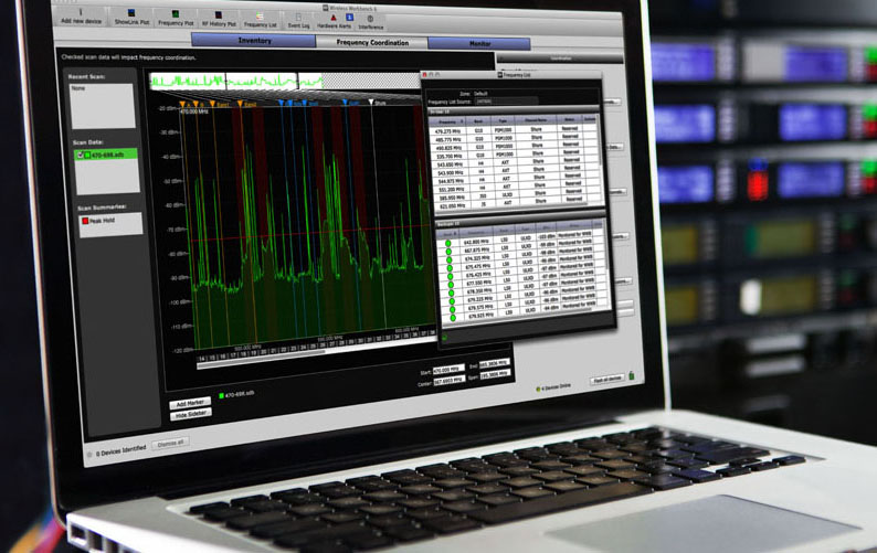

Editor’s Note: For the uninitiated, Wireless Workbench 6 (WWB6) is designed to offer total control of networked Shure wireless systems to provide an interface to manage every facet.
“I’ve got everything loaded into the INVENTORY section, I can get them to talk to Workbench but I don’t know what to do from there,” said the person who was the guitar player, production manager and RF coordinator for the first opener of my most recent tour.
This comment is probably the most common statement when I talk to WWB6 newcomers. There’s a lot going on; it’s a powerful tool, and you can really dig yourself into hole with it as well if not used correctly.
The following is a walk-through to get you past the second step: Frequency Coordination. There’s a lot of information not discussed because this is a “down and dirty, just to get you rolling” kind of thing. Some of the steps may seem redundant but they’re included to confirm you’re working in the correct areas in order to possibly save time and frustration. Once you get comfortable with this process, do a bit of research and expand your knowledge.
Let’s begin. At this point you’ve connected everything properly, have the antennas placed and Workbench is “talking to the wireless rig.” Most importantly, make sure the microphone and bodypack transmitters are off and that the in-ear monitors are not transmitting; however, be sure to turn on any other RF units that will be used during the show. Don’t forget about things like video walls because some emit RF when operating, as well as wireless systems that may not be part of your rig.
The first thing I do is reconfirm my network. At the bottom left of the screen, click the button FLASH ALL DEVICES. This will cause your networked RF units to blink wildly as if you’ve won the jackpot. If it’s meant to be networked and doesn’t blink, it’s time to fix that problem before moving on.

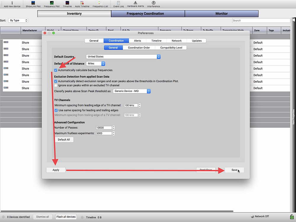
The next thing is to check that the frequency calculator is set to automatically look for back-up frequencies. It’s always good to have a back up, as many as you can get.
To find this option, go to the top of the screen to the WIRELESS WORKBENCH 6 dropdown menu. Click PREFERENCES, click COORDINTION, click GENERAL (found just below COORDINATION) and then confirm that the AUTOMATICALLY CALCULATE BACKUP FREQUENCIES box is checked. Click APPLY at the bottom left of the window, then click SAVE at the bottom right. Time to make the donuts.
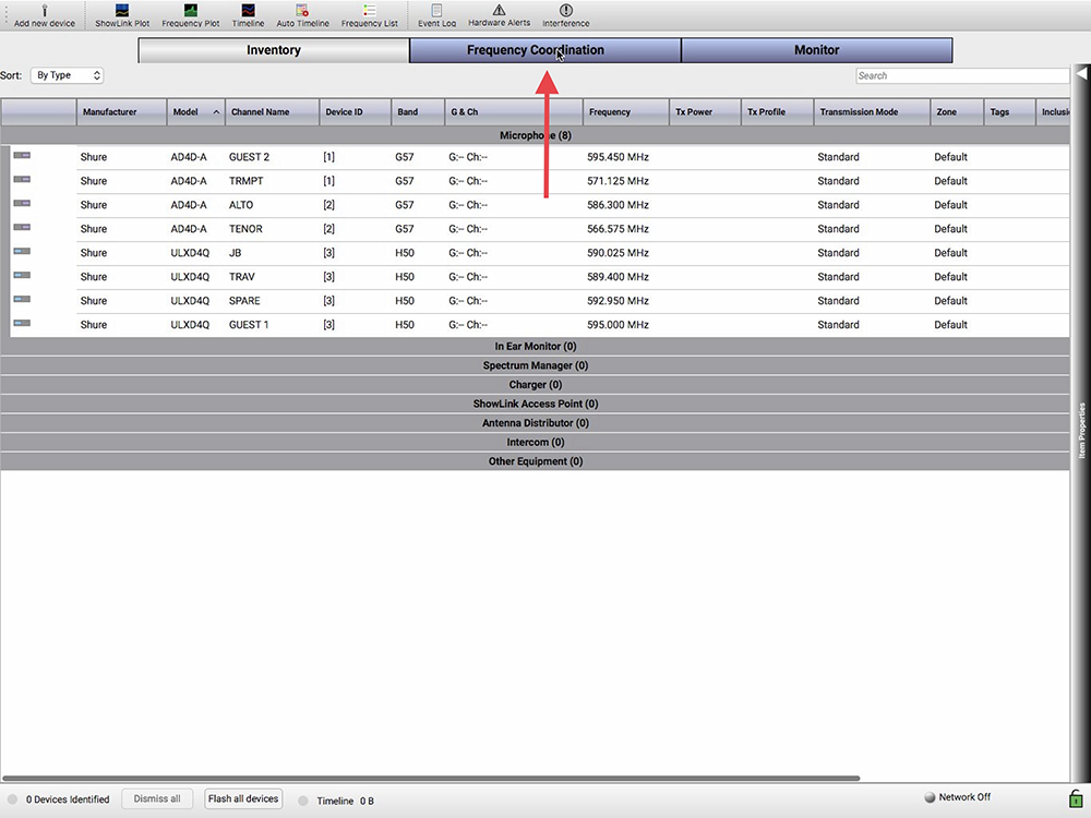
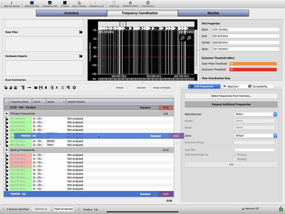
1) Click on the FREQUENCY COORDINATION tab near the top of the window. Note the window is broken up into five sections — three on the top half and two at the bottom.
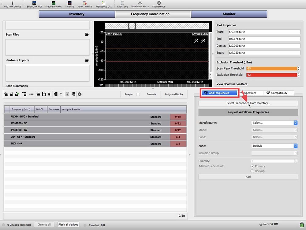
2) In the bottom right section, click ADD FREQUENCIES, then, just below, click on the SELECT FREQUENCIES FROM INVENTORY… button. This opens the COORDINATION CHOOSER window.
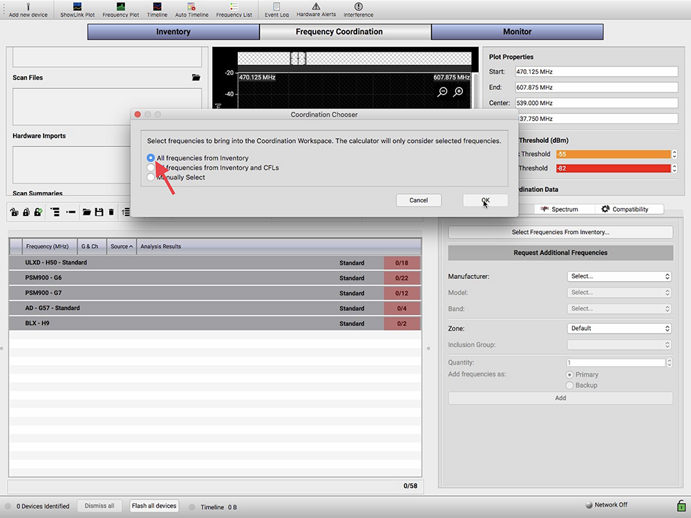
3) Select the ALL FREQUENCIES FROM INVENTORY button, and then press OK. This will populate the bottom left section. Go to the bottom left section, the COORDINATION WORKSPACE and locate and click the EXPANDS ALL button. It’s the first button to the right of the padlocks, and looks like three stacked horizontal bars with a small down-arrow on the upper left side. You will now see your channels and frequency information.

4) This is the first of two opportunities to perform some triage. The frequency calculator will find frequencies in order as they appear in the Coordination Workspace. If this doesn’t suit your needs, for example, if a more important channel is in a lower group, you can click-and-drag it to a higher location. I find it best to start at the top and work down in your preferred order as, occasionally, Workbench will flip things around unexpectedly. We can perform a more specific triage for each channel at a later time.
5) Next let’s move our attention to the top left section, just below the INVENTORY button to RECENT SCANS and click the cog to the right. This opens the LIVE SCAN SETTINGS… window. Here, under the MICROPHONES heading, is a list of available units to perform your scan. Take care when selecting the unit(s) to perform the scan because you want to cover as much of the frequency range as possible.
Look at the far right of the column labels for START and STOP. These columns denote the frequency range that each device can cover. Make sure to select as many of the devices required in order to cover as much of the spectrum as possible. Shure Axient products will cover the entire spectrum and due to this are very handy for performing scans.
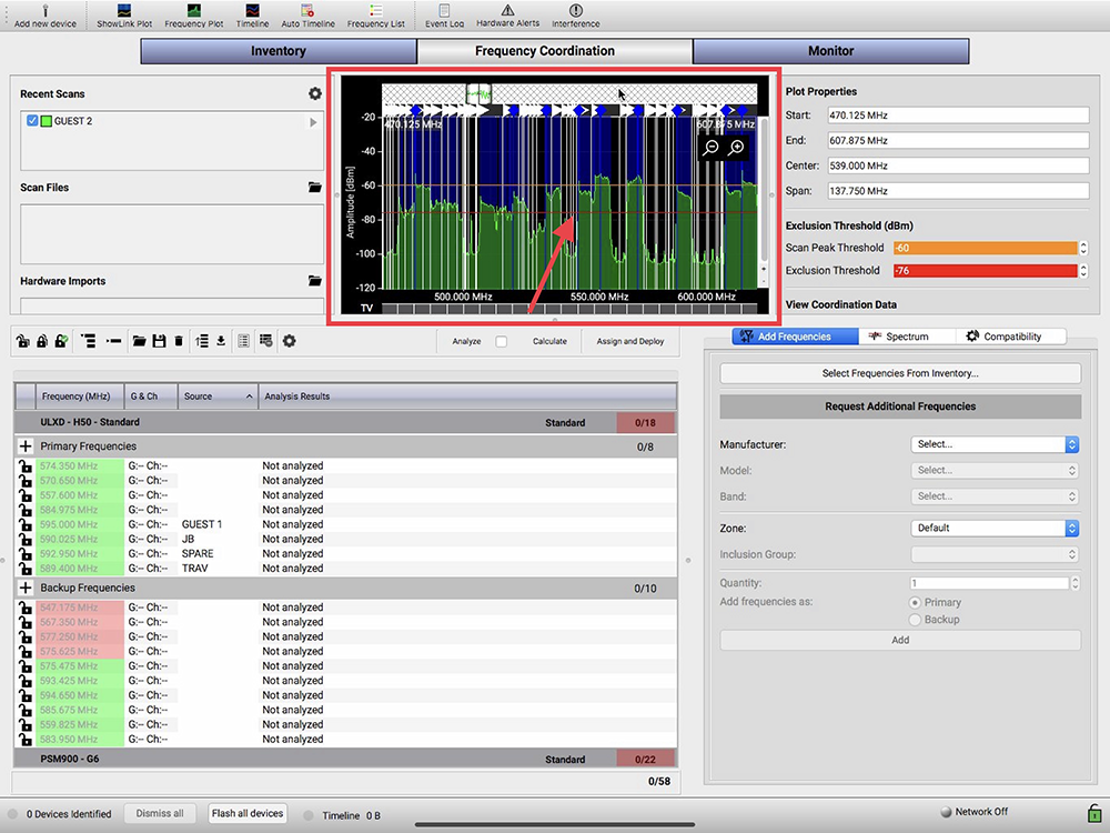
So, with our units selected to cover as much of the spectrum as possible, find the START button on the bottom right and click it. The window will close and, if you turn your attention to the top center to the FREQUENCY PLOT area, you will see the plot being displayed in green as the RF unit(s) scans through the frequencies. The green represents frequencies already in use by sources other than yourself. You did turn off the mics, packs and IEM transmitters, right?


6) Now go to the top right section, below the MONITOR button, find PLOT PROPERTIES and scroll down until you can see the EXCLUSION THRESHOLD (dBm) section. First, confirm the Scan Peak Threshold, the orange bar, is set to -60.
Next, we will work with the EXCLUSION THRESHOLD. If you look back to the FREQUNCY PLOT area, you’ll notice two thin lines, one orange and one red. These are the Scan Peak and Exclusion Threshold levels. I find my mics transmit at about -60 dBm, so I lower the EXCLUSION THRESHOLD in an attempt to at least exclude everything operating above -80 dBm. I go as low as I can to exclude all the unwanted frequencies and ranges that seem problematic, the ones getting close to that -60 dBm range.
The blue shading represents the excluded ranges and frequencies. This is an opportunity to get into some trouble. Exclude too much and there may not be enough spectrum left over for all your channels; don’t exclude enough and it may produce unwanted results. This is more an issue for those running a high number of channels or if the available spectrum is tight.
The mic will operate at around -60 so even if the plot shows RF at -80 or higher, the calculator may still find usable frequencies in that area. Remember, the stronger signal always wins. Having said that, after we calculate the frequencies, you may have to go back and adjust the EXCLUSION THRESHOLD to be able to include more of the spectrum. More on this later.

7) So your scan is complete, you’ve excluded some problem areas from your available spectrum; it’s now time to get those frequencies.
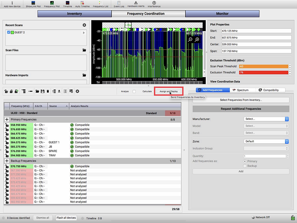
Lets go back to the COORDINATION WORKSPACE, the area at the bottom left. There’s the CALCULATE button located along the toolbar, almost dead center of your computer screen. Click on it. Looking to the bottom of the COORDINATION WORKSPACE, there’s a blue progress bar.
This bar will cycle a few times, trying different combinations in an attempt to get you the most frequencies before eventually stopping. I have an older computer so this gives me an opportunity to hit catering for a coffee It literally takes my machine that long. It’s a powerful program, and my computer is slow.


Once the progress bars have completed cycling, there will be, hopefully, a complete set of clean, intermod-free frequencies, including a number of back-ups. I say “hopefully” because this is dependent on the available spectrum. If you feel you don’t have enough frequencies, it may be possible to obtain a few more by adjusting the EXCLUSION THRESHOLD. Keep an eye on the blue shading. As you raise the threshold bar you’ll see the shading disappear, increasing room in the spectrum, so long as it is rising above the green areas. Do another calculation by hitting the CALCULATE button again and get another coffee. Continue the process until you’re satisfied with the results.
8) We’re almost done, just a few keystrokes away now. Locate the ASSIGN AND DEPLOY button; it’s part of the COORDINATION WORKSPACE toolbar and is in the center of the computer screen. Pressing that button will open the ASSIGN AND DEPLOY window. This provides the opportunity to perform our second — and more specific — triage.
Note the RF units are listed under ASSIGNED CHANNELS. There are two columns just to the left of the assigned channels: the RANK and dBm columns. RANK provides a general judgment of the strength of the RF quality for that particular channel, while dBm offers a more specific idea of the quality. As you may have guessed, the higher the dBm level, the better the better the signal will carry. You may want to reserve these channels for the more important persons. WWB6 assigns them first to last, utilizing the best-found frequencies, as they’re programmed into the RF units.
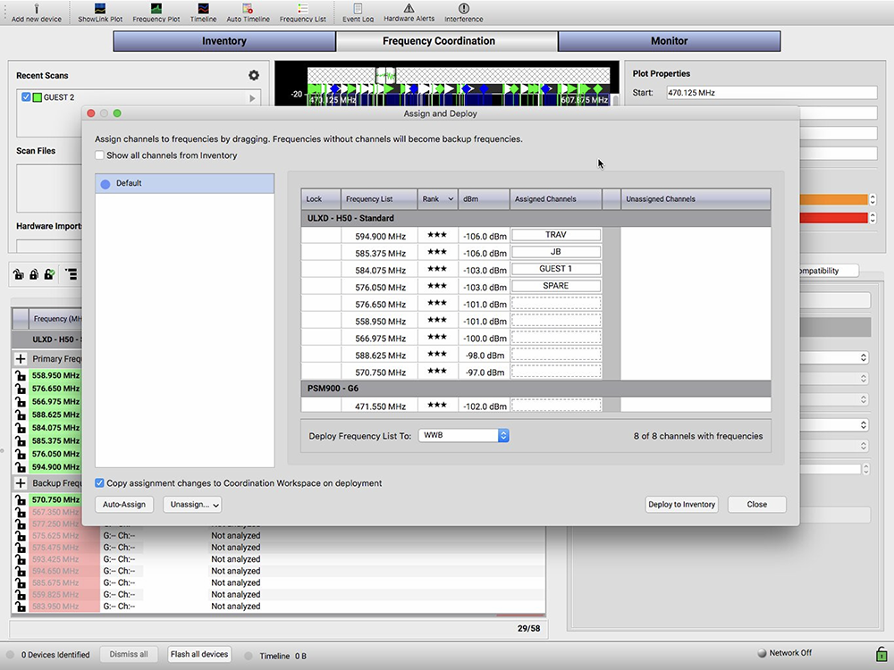
You’re able to change the order via two methods. One is to pull the frequencies into the UNASSIGNED CHANNELS column and then back to the ASSIGNED CHANNELS column in the preferred order. The second is to simply drag them into the position where you want them to be. (Personally, I feel the first method is the easiest and quickest.)

Once this task is complete, confirm the COPY ASSIGNMENT CHANGES TO COORDINATION WORKSPACE ON DEPLOYMENT box has been checked. This is found in the bottom left of the window. Next, move to the bottom right, locate the DEPOLY TO INVENTORY button and click it.
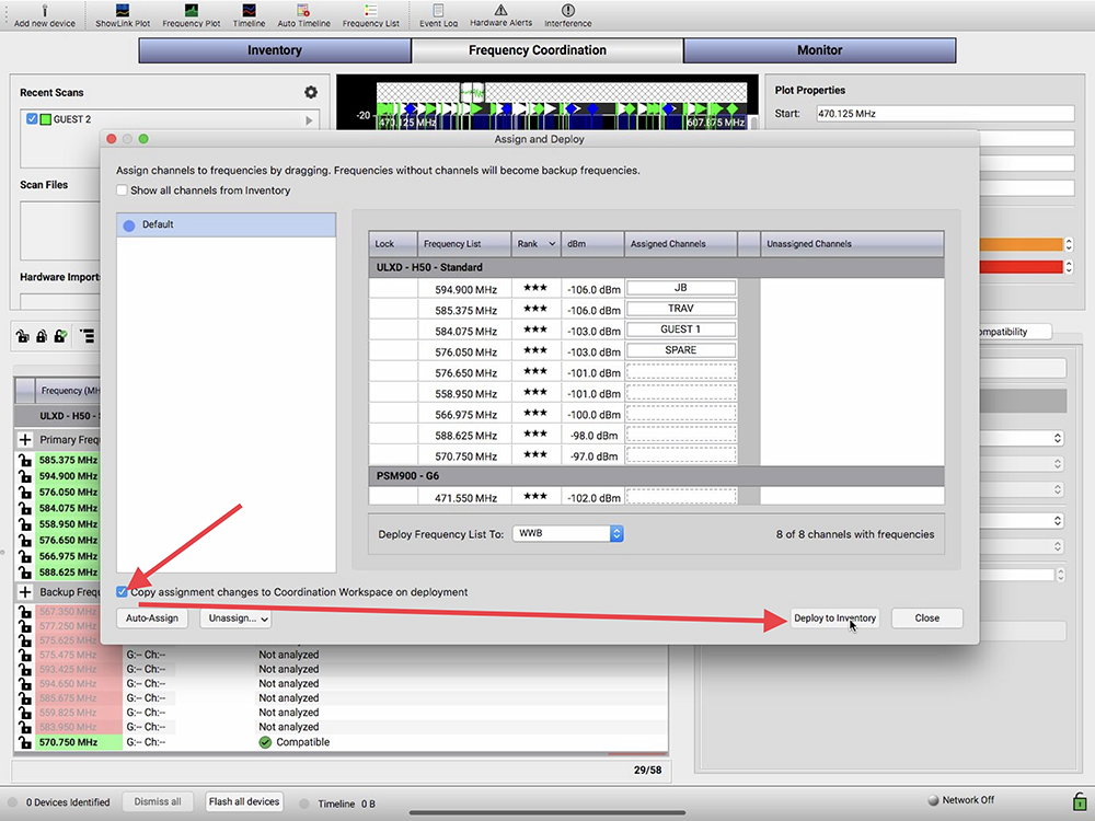
9) Workbench has now pushed all those new frequencies to the RF units, causing the front panels to flash, and has also opened the DEPLOY TO INVENTORY window, confirming the process.
10) Press OK to close the DEPLOY TO INVENTORY window, press CLOSE to get out of the ASSIGN AND DEPLOY window, and start synching your transmitters.