
Electronic correction in the form of Equalization (EQ) is one of the most useful audio tools for loudspeaker compensation/correction, whether it compensates from non-linearities in the loudspeaker or for altering the effect of room acoustics.
Two audio filter types are typically used: IIR and FIR. IIR stands for Infinite Impulse Response and FIR stands for Finite Impulse Response. Each has its own pluses and minuses. This article intends to introduce key terminologies and outline few basic uses of FIR filters for audio system optimization.
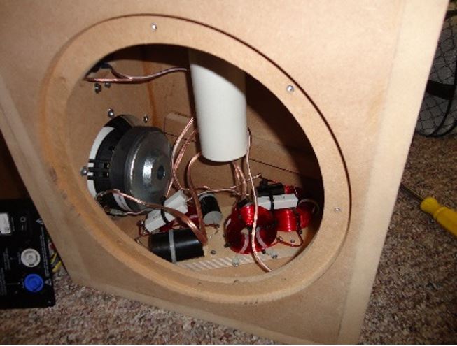
The IIR filter is based on the idea of an analog/passive filter and has minimum phase characteristics. An example of a passive crossover typically found in a loudspeaker is shown in figure 1.
The IIR filter is common and can be used in the passive/analog domain and in a digital signal processor (DSP). Several common terms that relate to IIR (some relate to FIR too) are: passive/analog crossover, minimum phase filter, analog graphic/parametric EQ. FIR filters on the other hand are commonly implemented in the digital domain.
Phase Response
An IIR filter has a minimum phase characteristic. Minimum phase is a condition where the phase response and frequency response are related by the Hilbert Transform (predictable from each other). In IIR, changes in frequency response will produce changes in the phase response. The minimum phase response is the least amount of phase shift possible for a given magnitude response.
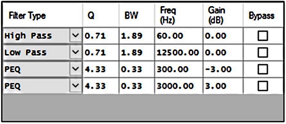
Figure 2
Figure 3 – the right graph shows the frequency response (red curve) and the phase response (green curve) of the IIR filter. As previously discussed, the changes in magnitude are followed by changes in phase, thus the phase response has its own shape.
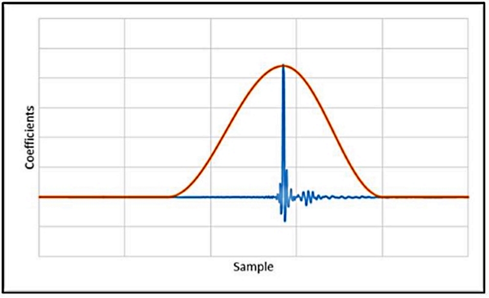
Figure 3 – the left graph shows the filter’s impulse response which has a peak very close to 0ms. Typically, there is minimal processing delay introduced by an IIR minimum phase filter.
A digital IIR filter is setup as shown in figure 2, containing a high pass filter (HPF) at 60Hz, Butterworth 12dB/oct, a low pass filter at 12500Hz, Butterworth 12dB/oct, a -3dB 1/3oct wide peak EQ at 300Hz and a +3dB 1/3 oct wide peak EQ at 3000Hz. This table is a screenshot from Filter Hose.
The reader can observe the transfer function (figure 3 – right) and the zoomed filter’s impulse response (figure 3 – left).
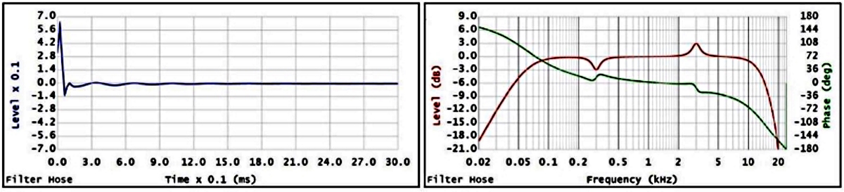
Figure 3
Side note: Not all IIR filters are minimum phase. All Pass Filters are non-minimum phase IIR filters.
An FIR filter can also create a similar transfer function as shown in figure 3.