

Let’s delve into the world of loudspeaker design, starting with the fundamental ideas behind drivers and cabinet design, covering a range of subjects that includes:
• Frequency response and impedance graphs, and how to interpret them
• Thiele-Small parameters – what they mean and how we can use them
• Loudspeaker simulation tools
• Loudspeaker design “dos” and “don’ts”
The focus will be on subwoofers for now, as they’re the simplest of loudspeakers to work with. While a 2-way (or 3-way) discussion would be very interesting to write about, passive crossovers alone have been the subject of many articles. That said, let’s dive in.
Graphs
First we’re going to cover something incredibly exciting: graphs. Some manufacturers provide series of graphs in the data sheets for their products, which can be rather useful if you know how to interpret them. So, we’re going to go through some graphs and what they mean with regards to how the product will actually sound.
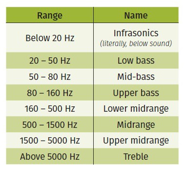
Figure 1 shows a list of frequency ranges and what they sound like. Please note that this is my own interpretation – others feel that certain labels are better for certain areas, but I’ll be using these terms and sticking to them.
The ideal frequency response curve is subject of discussion in the audio world. Some like a flat response – horizontal and smooth from 20 Hz up to 20 kHz; while cinema systems often work to a particular curve as recommended by the engineers at Dolby and the like. There’s also the B&K (Brüel & Kjaer) curve, among others.
When it comes to working with PA systems, I want one that’s as smooth and flat as possible. That way, whatever I’m doing at the mixing desk is reflected in the sound that’s coming out – working with a colored system is like trying to paint with color-tinted sunglasses on.
Whichever philosophy you subscribe to, everyone agrees that having a smooth frequency response is important. That is, free from any large peaks or dips.
Figure 2 shows a couple of frequency response graphs that I’ve measured myself. The exact details of the cabinet aren’t particularly important at this point. What matters is the information we can get out of the graph.
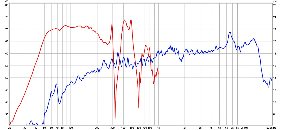
Let’s start with the red trace. In this case, we can see there’s a definite useful bandwidth, going from around 55 Hz before it starts to fall off in the bass, and up to around 200 Hz.
Above 200 Hz, the curve gets quite ragged, and actually has areas with very little output at all – if we were to play this cabinet full-range, the midrange would sound very colored indeed! We can also make an educated guess that this is a fairly small cabinet, given the limited low-frequency extension. It’ll have plenty of “punch” for most music, but will be found lacking when low bass is needed.
Given the limits of the data, we don’t know how this loudspeaker performs into the treble range, but given the midrange performance, it looks like it’s suitable for covering the low end of small systems, with 6- to 8-inch tops. As an aside, that’s exactly what I designed it for.
Next we’re going to look at the blue trace. This one has a single 4.5-inch full-range drive unit in a small cabinet. We can see a few features here:
• The overall rising response will sound quite “bright” or “thin” unless something is done to sort that out.
• A large spike in the 6 to 7 kHz range that will cause some sibilance and other high-frequency harmonics to stick out. A quick listen reveals that it’s rather distracting.
• A bit of a wiggle around 1.8 kHz, which isn’t as much of a worry as the 6 to 7 kHz spike.
• A little roughness in the 300 Hz range.
Now let’s turn our attention to impedance graphs. Figure 3 offers a couple of impedance curves. There’s not a lot going on with the red trace. A large spike indicates the driver’s fundamental resonance – if you tap the cone, that’s the frequency it will ring at.
Apart from that, the impedance drops again until it starts rising slowly towards the treble, which is a result of the inductance of the voice coil.

Looking at the blue trace, we can see a few features. The first of note is the large twin peaks, with a dip in the middle. When it comes to ported boxes, the dip is the interesting bit – the very bottom of that dip indicates the tuning frequency of the ported box, which is a very important bit of information (we’ll see why later). We can also see a couple of impedance wiggles above 150 Hz, which are likely resonances of the wooden panels of the cabinet, or perhaps internal standing waves.
T/S Parameters
Thiele-Small parameters (named after Richard Small and Neville Thiele) are a set of numbers that help to describe the behavior of a given loudspeaker at low frequencies. We don’t really need to know what all the numbers mean, just that they exist and can be entered into a variety of software packages that can predict the performance of the speaker in a chosen enclosure.
It’s good practice to measure the Thiele-Small (T/S) parameters of any drivers ourselves. That way, the simulations we produce are as close as possible to what will actually be built. The T/S parameters given in driver datasheets are often averages of a sample of the production run, so there may be some differences, but you can use them if you’re unable to measure the drivers yourself. Some of these parameters are useful to know about so you could look at a datasheet and quickly decide whether a driver is useful or not – I’ll pick them out individually in the next article.
Cabinets
There are lots of different cabinet designs. Some are sensible and work well. Others, not so much. I’ll outline a couple here, but there’s a lot of additional reading available on the internet.
Sealed boxes are the simplest. The air within the cabinet acts as a spring that provides restoring force to the cone, in parallel with the driver’s own suspension. The result is that the cone will exhibit a higher resonance than if it were in free air – the smaller the cabinet, the stiffer the air spring, the higher the resonance will be.
Sealed boxes are rarely used in professional audio applications, and with good reason – they don’t go particularly loud. The cabinet itself simply contains the rearward output from the driver, and the sound coming from the front of the cone goes out towards the audience.
Other types of cabinets provide more output by doing something useful with the sound from the rear of the cone. Sealed boxes do have a couple of things going for them, though: they can be very small, and they can provide some output down to very low frequencies. Output at 1 Hz is completely possible, although most drivers will only be able to produce it very quietly, as low frequencies require a lot of air to be displaced.
The most commonly used type of cabinet in pro audio is the ported box. The main advantage over a sealed cabinet is the increased output. While the extra SPL capability is usually only available over a fairly narrow range (of the order of 10 Hz), we can get about 10 dB more output than a sealed box. If we wanted to make up that difference, we’d need about three times (3x) the number of sealed boxes, with power amplifiers to match. Suddenly, the ported box seems like a very good idea. Another advantage is that the air moving in and out of the cabinet means the drivers can be kept a little cooler under high-power conditions.
There are a couple of disadvantages, too. The time-domain response isn’t quite as good as a sealed box – since the bottom end of a ported box is mostly from the port (which is part of a Helmholtz resonator), there’s a half-cycle of delay there. The audibility of that is contested.
Having personally tried both sealed and ported boxes using the same drivers and amplifiers, I can say that the extra output from ported boxes is much more useful than the sealed boxes being run hard into the limiters. The second disadvantage of ported cabinets is that below the port tuning frequency, the driver doesn’t really “see” the cabinet any more – the port just lets very low frequencies pass through without much resistance, so if the driver is subject to very low-frequency signals, it’s free to flap around.
At high power levels, this can cause mechanical damage – folded cones, torn suspensions, or smashed voice coils. Again, I know this from experience, having destroyed a top-end 15-inch subwoofer driver by subjecting it to test tones well below the port tuning frequency. The fix is that a high-pass (low-cut) filter must be used to cut down the signals below the tuning frequency so they don’t pose a problem for the driver.
Simulators
When the T/S parameters were first starting to be used, the results of the equations would be something like Fc = 58 Hz, Qtc = 0.8. An experienced loudspeaker designer will know what that curve will look like, but even so, having to put a load of numbers through some equations to figure out if a cabinet will have the frequency response you’re looking for isn’t a wonderful way to work.
Today, there’s quite a lot of software available that will take the T/S data of the chosen driver and then show the frequency response that will be achieved with that driver in the chosen cabinet. You can then optimize as you like.
In my experience, there are three “levels” of simulation software. First are online calculators that take in the bare minimum of T/S parameters (usually just three of them!), and spit out a recommended cabinet volume and port tuning frequency (if you’ve selected a ported box). I’d recommend avoiding those – you don’t know what frequency response they’ve aimed at, or how close they’ve gotten.
Next are the majority of loudspeaker simulators. These usually take the full complement of T/S parameters, and also usually recommend a couple of different cabinets and draw the resulting frequency response graph. It’d be impossible to audition them all, but I’ve worked with WinISD Pro, which is a good piece of software – it will show you what happens at different power inputs, including showing cone excursion, and will allow you to add EQ and other filters. Software like this is a good place to begin.
The final level has the most complicated simulators that can predict the performance of any cabinet you can think of. My go-to is Hornresp, which has been put together by David McBean, working with the DIY community. Hornresp presents the user with a pair of chambers and four “sections” with which to describe the chosen cabinet.
While that sounds fairly limited, the possibilities are virtually endless – WinISD only goes up to a pair of chambers! Hornresp is an exceptionally powerful piece of software that’s being constantly developed, and I recommend anyone seriously interested in loudspeaker design to learn to use it.
If you want to graduate past Hornresp, the last bit of free software I’m aware of is Akabak. The learning curve is legendary, but in theory you can simulate anything – there’s no limit to the number of parts of the cabinet. I find Hornresp to be a happy medium with some neat features, and will be using it for the later parts of this series.
Design Guidelines
We’ve covered quite a lot of ground, with an idea of the purpose of T/S parameters, which software we might like to use, and why.
Here are some guidelines that will help to make sure the cabinets we design work well.
• Let’s begin with bass reflex port sizing. You’ll find you can get a nice flat response with a particular tuning frequency and that you could either use a very wide and long port (which must be accounted for in the overall cabinet size), or a very small one that could just be a hole drilled into the cabinet. The tuning frequency would be identical, but consider this – at the tuning frequency, almost all of the sound from the cabinet is coming from the port.
• Trying to shove all of that air through a small port will be a problem: it’ll encounter a lot of friction at high levels, which means some output will be lost. A good design will ensure that the air speed in the port stays fairly low, even at full power. That’s more important with subwoofers, where most of the power input will be somewhere near the port tuning frequency. Full-range cabinets are subject to much wider bandwidths, so there’ll be less power in the bass. Most simulation software can show the air velocity – make sure you check with the expected power inputs.
• Next, don’t try to go too low. You might find that a particular 12-inch driver gives a fantastic response in a huge cabinet tuned to 20 Hz. That might be fine for a home theatre system, but we work in pro audio where the priorities are quite different.
• Generally, we want small and loud cabinets. For every octave down, we need four times (4x) the cone excursion, which is a difference of 12 dB in output. A quick simulation suggests a good 12-inch driver would manage 107 dB in a cabinet tuned to 20 Hz before running out of cone excursion. Take the tuning up to 40 Hz and it’ll make it up to 119 dB, which is much better for our purposes.
• Hoffman’s Iron Law – small cabinet, efficient, low bass – pick any two. This is something we’re constantly working against. Spending more money on better drivers improves the situation, but there are still limits.
• Generally, I start off by deciding how low I want to go, and then picking the trade-off point between size and efficiency. Note that efficiency is directly related to output – if everything stays linear, a 93 dB SPL at 1 watt/1 meter loudspeaker with 1,000 watts input will reach 123 dB, while a different cabinet might be 97 dB SPL at 1 watt/1 meter and reach 127 dB with the same power input.


