A block diagram of a sound system is a simplified drawing of the system components and their connections.
It shows the signal flow from inputs to outputs (generally from left to right).
You could call it a “road map” of your sound system.
If you are designing a sound system from scratch, a block diagram is the starting point. You can use it to generate a list of necessary components.
Also, with a block diagram you can easily see where to wire in new pieces of equipment.
Perhaps most important, a block diagram is a tremendous aid in troubleshooting the system.
In this article I’ll describe how to create a block diagram, and how to use it to troubleshoot a sound system. You can sketch a block diagram with a pencil or draw it more neatly with a computer drawing program such as Windows Paint, Adobe Illustrator, Autocad, and so on.
Block Diagram Examples
In a block diagram, each component in the sound system is represented by a symbol, such as a mic, triangle or rectangle. Lines between the audio components are the cables. You can design your own symbols, and some typical ones are shown in Figure 1.
Figure 2 shows a block diagram of the simplest PA system. At the left of the diagram is the signal source: a microphone. The mic signal goes to a mixer, where the signal is amplified up to line level. Then the line-level signal goes to a power amp, which boosts the signal to speaker level. Finally, that speaker-level signal feeds a passive 2-way loudspeaker (one with an internal crossover).
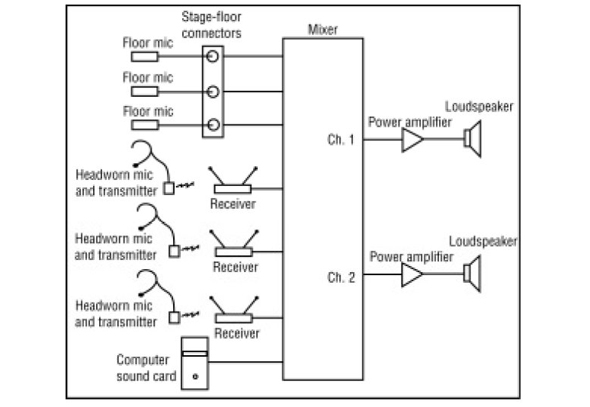
In Figure 3, we added more components to simulate a more realistic PA system. It has three floor mics, three wireless headset mics and three receivers. The floor mics are plugged into the stage-floor XLR connectors. A multi-conductor cable from those connectors goes to the mixer.
Also connected to the mixer inputs are the three receivers. One more input connection is to a sound card’s line output, which provides sound effects from a computer program.
To the right of the mixer are two channels of power amplification (probably in one stereo power amp). Each channel drives a passive loudspeaker – one on stage left; one on stage right.
Things get more complicated (but more realistic) in Figure 4.
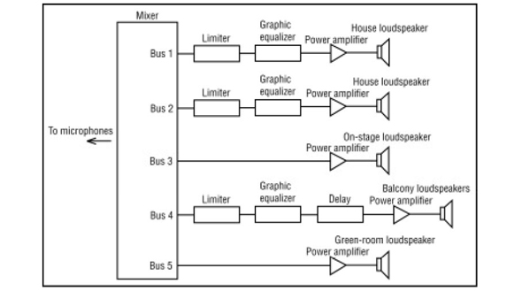
In this system, the mixer operator is using five output buses or channels:
• Buses 1 and 2 are for the house speakers (left and right).
• Bus 3 is for an on-stage speaker that plays sound effects.
• Bus 4 is assigned to some balcony speakers.
• Bus 5 feeds a speaker in the green room for cues.
As shown in the block diagram, the house-speaker signal from mixer Bus 1 feeds a limiter that protects the speaker from overly loud signals. Same for Bus 2. From the limiter, the signal goes through a graphic equalizer, which is used to notch out feedback frequencies.
The output of the graphic equalizer is amplified and drives a passive loudspeaker. The two graphic equalizers shown could be the two channels of a stereo unit.
Bus 3’s signal is amplified and sent to a speaker on stage. That way, the audience will localize certain sound effects on stage, rather than from the house loudspeakers.
The Bus 4 signal is limited, equalized, and delayed to prevent localization of the sound at the balcony speakers.
In the delay unit, the delay is set to the travel time of sound between the stage and balcony speaker, plus a few more milliseconds. This delay makes the audience hear the sound not from the balcony speakers, but from the house speakers up front.
Finally, Bus 5’s signal is amplified and drives a cue speaker in the green room.
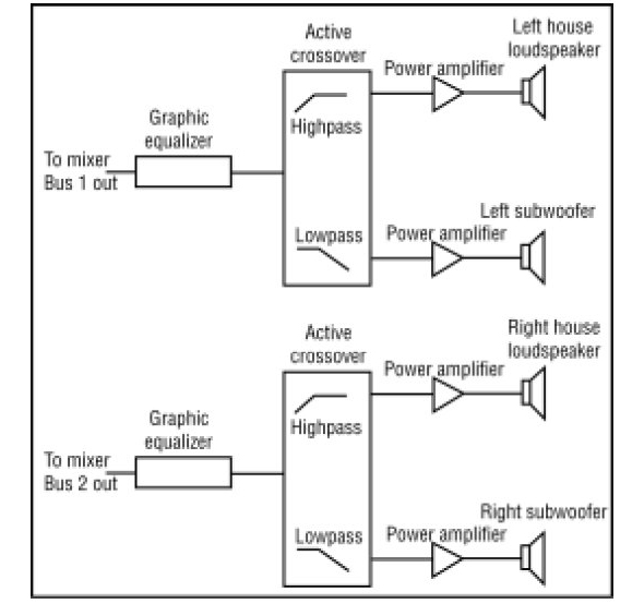
Figure 5 shows the output section of a system with an active crossover. The output of the graphic equalizer feed an active crossover, which divides the audio spectrum into two or three bands (lows, mids, highs).
In a typical system, you might use a low-pass filter to send signals below 120 Hz to a subwoofer, and use a high-pass filter to send all signals above 120 Hz to a 2-way passive house
loudspeaker.


