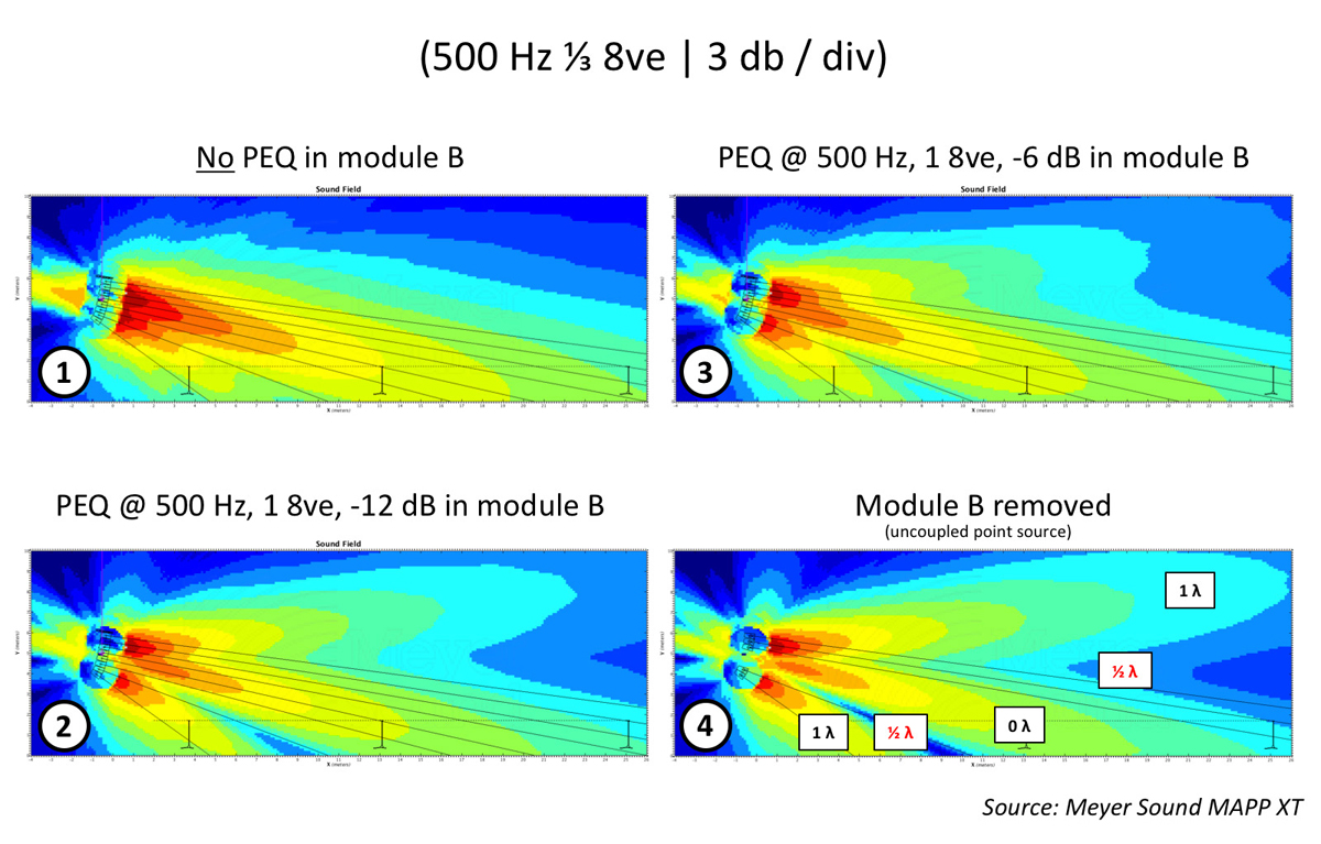

Whenever we experience too much of a particular frequency or frequency range, we’re tempted to resort to equalization to resolve the situation. In this article, we’ll see that the effectiveness of EQ relies entirely on the relative level separation from other sources.
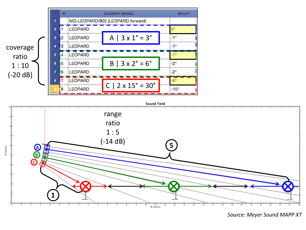
I design line arrays (Figure 1) as modular composite coupled point sources. Each individual module is effectively a perfect symmetrical arc. The splay angles are purposely set to achieve a 6 dB level drop (Figure 2, Plot 6), front-to-back, in the frequency range where the waveguides become sole custodians (typically 2 kHz and up).
Mid and high frequencies approximate cylindrical wave behavior (3 dB per doubling distance) up to a certain distance, and this way, the low frequencies that are typically bound to spherical waves (6 dB per doubling distance) for finite-length arrays have a chance of keeping up, once their loss rate has been decelerated by LF buildup/room gain (not shown in SPL plots).
With the waveguides as sole custodians, designing line arrays is a relatively simple matter of “point-and-shoot” (amplitude steering). Unfortunately, at low frequencies, single line array elements are effectively omnidirectional. This renders them immune to rotation and therefore splay. Instead, the overall array geometry is the driving force (phase steering) behind low frequency control.
Ultimately, vertical pattern control is achieved by committee. It’s a balancing act of “beam-narrowing” in the low end versus “beam-spreading” in the high end. Vertical pattern control begins with roughly 72 degrees (Figure 2, Plot 4) at the frequency whose wavelength matches the length of the array (number of loudspeakers times their spacing).
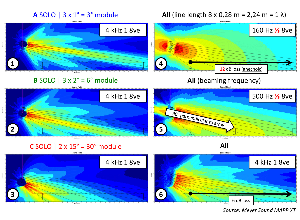
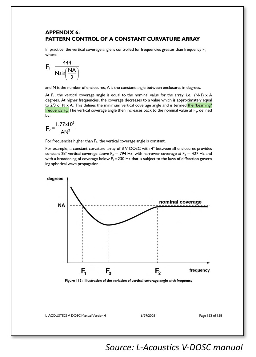
Conventional arrays, however, tend to do a little too much of a good thing after the onset of pattern control. L-Acoustics refer to this as the “beaming frequency” (Figure 3) since the introduction of the V-DOSC line array in the early 1990s. For this particular array, the beaming frequency is approximately 500 Hz (Figure 2, Plot 5).
We can clearly see a concentrated beam of energy, perpendicular to the entire array, overshooting the beginning of the audience and making a nosedive before the end of coverage. This beam is typically about one-third narrower than the array’s nominal coverage angle observed at higher frequencies.