Figure 4 shows the “raw” anechoic system response (no processing). The traces have been aligned by means of an offset in order to assess uniformity. In reality, frequencies below line length (160 Hz) will show matched responses with help of LF buildup/room gain.
Local HF attenuation caused by humidity is proportional to distance and can easily be remedied with EQ, provided the array is subdivided in zones, which the modular composite coupled point source happens to be.
In practice, this design approach will result in matched traces for half of the array’s operational range in exchange for 6 dB of level variance front to back, leaving only the decade centered around the beaming frequency, which depends entirely on the geometry of the array.
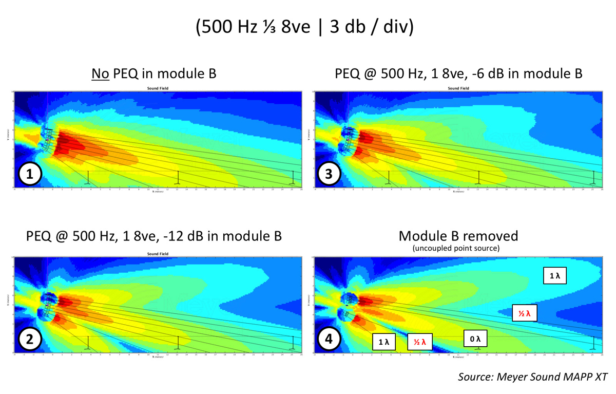
In this specific frequency range, 6 dB of local tonal variance is observed. The bulk of this energy is concentrated in the area halfway through the audience. Suppose we were to resort to EQ in attempt to even out the response over space by attenuating the offending frequencies in this part of the audience (B module) exclusively.
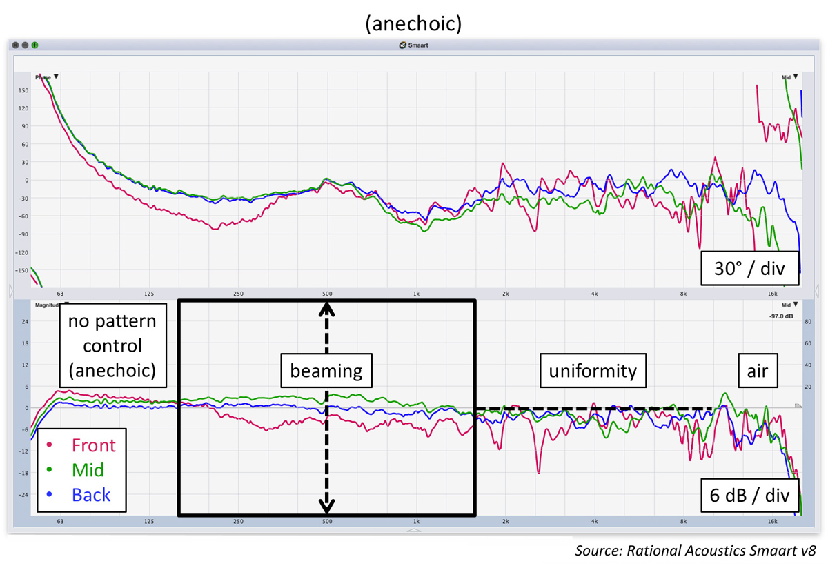
Figure 5 clearly shows that an octave-wide cut at 500 Hz in the B module has limited merit. It reduces the tonal variance to some extent but doesn’t really address the concentrated energy halfway through the audience.
If anything, it appears to make these frequencies go down in level everywhere throughout the entire coverage area. In addition, there’s also the onset of a particularly nasty octave-wide cancellation at 315 Hz. What’s going on?
