The proper way to connect this type of active-balanced output to an unbalanced input is to simply leave pin 3 disconnected.
Signal voltage appears between pins 1 and 2, which is just what our unbalanced input wants. This is another instance where you’ll probably need to modify or custom-build a cable if the output is on an XLR connector.
If you have this type of balanced output on a TRS jack, you can usually use a TRS-TRS cable to connect it to an unbalanced input. A TS (unbalanced) jack at the input makes no connection to the plug’s ring, which will leave it floating, as we desire.
However, some manufacturers thoughtfully use a TRS jack for an unbalanced input, wiring the jack’s ring contact to ground. This assures that you’ll get signal between the unbalanced input and ground when using TRS-TRS cable to make the connection from a balanced output. It works fine for certain types of balanced outputs, like our friend the transformer, but since it grounds the inverted output, it can be a problem for the simple inverting/non-inverting op-amp configuration.
It’s from this type of balanced output circuit that the “you lose half your level” factoid originated. Since you’re using only one half of the bipolar (±) output, you’re using only half of the unit’s designed output voltage. If the spec sheet says that the maximum output level is +22 dBu, that’s the voltage measured between pins 2 and 3, or tip and ring. With pin 3 unused you’ll only see half the voltage, or +16 dBu, before the output circuit runs out of steam.
Using half of an output can also throw off your metering. It’s fairly common for 0 on a VU meter to represent the nominal output level, typically +4 dBu for a professional balanced output. When the source’s output meter (if it has one) reads 0, the meter on the destination’s input (if it has one) that’s getting only half the total output signal will read -6. The common complaint here is that you can’t get full output from your A/D converters if they’re calibrated for the typical +20 dBu in = 0 dBFS, resulting in half-height squiggles in your DAW waveform display.
Another electronically balanced configuration uses what’s often called a “cross-coupled” or “servo” balanced circuit. This generally uses three op-amps and delivers the full voltage between pins 2 and 3, even with one of those outputs connected to ground, the same as when unbalancing a transformer output. This output-circuit configuration was designed to emulate the effect of a transformer, and while it’s far less expensive than a good transformer, it requires a few more parts than a simple op-amp inverter. When connecting this type of output circuit to an unbalanced input, pin 3 should always be grounded. This effectively puts the two legs of the output circuit in series. By grounding pin 3, the full signal voltage, rather than half, will be seen by an unbalanced input connected to pin 2 and ground.
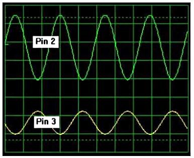
In a well-trimmed, cross-coupled output circuit, the outputs will be truly symmetrical— both will be measure the same voltage to ground—but this isn’t an essential requirement. Although the difference between the non-inverting and inverting outputs will always be correct, the outputs may have different voltages, as seen in the scope trace. Leaving pin 3 floating can result in an unpredictable (rather than half the nominal) voltage at pin 2. It can get ugly when nearing the maximum output level: The higher-level output of the two will clip before the lower-level output. Equally nasty is that if the circuit isn’t trimmed for equal output levels, a left-right stereo pair could put a centered source off-center. If you have this type of output, always connect it to a differential (balanced) input or tie pin 3 to ground.
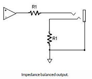
One method of creating a balanced output is so simple it seems almost like cheating, and indeed, some condemn it as such. (It’s a popular comment in online forum “reviews.”) But it’s not cheating at all, and it works quite well. The output signal is connected only between pins 1 (ground) and 2. A resistor equal to the output impedance of the op-amp driving pin 2 is connected between pins 1 and 3. This satisfies the balanced output requirement of equal source impedance for pins 2 and 3. How well it works is a function of how accurately the “dummy” impedance on pin 3 matches the active source impedance, but that’s easy to do with inexpensive 1% tolerance resistors, and most manufacturers who use this output configuration do it right.
Since with this configuration the signal voltage on pin 3 is always zero, there’s always a voltage difference between pins 2 and 3 (unless of course the signal voltage is zero), which is just what the differential amplifier at the input of the next device in the chain wants to see. While you’ll occasionally find a balanced XLR output configured this way—it works so well that it’s even used in a couple of pricey microphones—it’s more commonly found on balanced ¼-inch TRS output jacks.


