Usually you can identify an unbalanced device by examining its input and output connectors, though this is getting more difficult with the type of connectors and construction used in modern audio gear.
“Mono” ¼-inch phone jacks and RCA “phono” jacks are inherently unbalanced, since their shield terminal is physically attached to the chassis.
For gear built in a plastic box, one jack terminal is nearly always wired internally to the signal ground point. In an unbalanced connection, which almost always is made with a shielded cable, signal current must flow through the cable shield in order to complete the electrical circuit.
A good shield can be a pretty effective barrier for electrical noise, but with an unbalanced connection, any noise that gets through the shield or is carried along it will be passed through the chain, just like the desired signal.
A balanced output may be described as transformer balanced, electronically balanced, floating, servo balanced, differential, or symmetrical.
These are different circuit topologies, all of which provide two output connections with the equal source impedances required for a balanced connection. With certain topologies, the voltage on least one (or sometimes both) of the two signal leads is also referenced to ground, but that’s incidental and not a requirement for a balanced output.
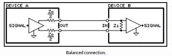
A balanced output always consists of two leads, neither of which is connected to the equipment ground. The input of the device receiving the balanced signal sees the voltage between the two signal leads. The cable shield, unlike with an unbalanced connection, carries no signal current (at least, it’s not supposed to). The cable shield is connected to the equipment’s chassis, and it becomes the reference point for any noise voltage picked up by the cable on its way to the next link in the signal chain.
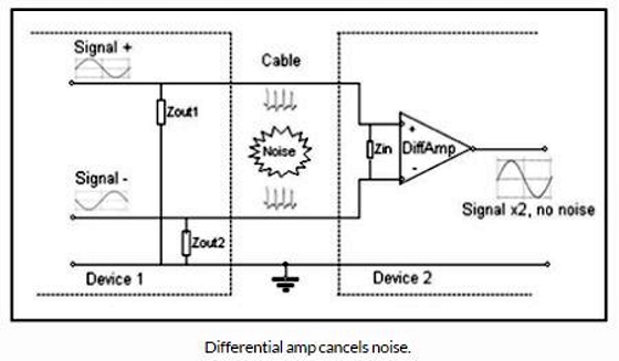
On the receiving end, the signal is applied between the two inputs of a differential amplifier or a transformer at the device’s input, rather than between a single point and ground. The output of the differential amplifier, as its name suggests, is the difference between the two inputs.
What gives a differential input its advantage is its ability to cancel out common mode noise, that is, noise (unwanted signal, really) that’s identical on both signal leads. Since the difference between the same two numbers is zero, any noise added to both signal leads will be cancelled. This not only includes noise picked up by the wires, but also noise on the ground, since the ground may be common to both inputs.
Since we’re concerned with amplifying the difference between two signals, one of them can be zero (at ground potential) all the time, and you’ll still have a difference (signal voltage minus zero) at the output of the differential amplifier. More about this shortly.
Remember that what defines a balanced connection is that the source impedance of each of the two output-signal leads referenced to ground must be identical. Here’s how a differential input works in our favor:
Let’s focus on the electrical circuit connecting the two devices. Signal current from Device 1 flows through input impedance Zin of the differential amplifier at the input of Device 2. The voltage across Zin is amplified by the differential amplifier. This is the normal desired signal path.
This diagram shows Device 1 with what’s known as a symmetrical output configuration. Each lead carries the same signal voltage but with opposite polarity. When one leg of the output is +1 volt referenced to ground, the other is -1 volt. Subtract them in the differential amplifier (remember your high school algebra?) and what you get is double the voltage on either leg measured with reference to ground. But it doesn’t have to be this way, as we’ll see a little later.