
Part 2: Smart Loudspeaker Acoustic Measurements
When conducting audio tests, it’s generally a good practice to adhere to industry standards or to at least use them as a guideline. Smart speakers are so new that there are currently no industry standards for testing them. However, in terms of form and function, a smart speaker is similar to a speakerphone and there are several national and international standards which focus on speakerphone tests such as IEEE 1329.[1] These standards can be used as a guideline when testing smart speakers.
Inner Path
As previously noted, for the primary input path of a smart speaker, a speech (or speech-like) signal is sensed with the device’s microphone array, digitized and uploaded to the Intelligent Virtual Assistant (IVA) for signal processing and command interpretation. An audio test of this path involves “tricking” the device to acquire and save a test signal, retrieving the recorded signal from the back-end server, and comparing it to the original test signal.
Figure 1 shows a test setup which is based on IEEE Standard 1329. The standard specifies that speakerphones be tested on a tabletop approximately 1 meter wide x 1 meter long (39 x 39 inches) in an anechoic chamber or in a simulated free field (using time-selective measurement techniques). For the send direction (the equivalent of the smart speaker input path), the device is positioned 40 centimeters (15.7 inches) from the edge of the table, with a mouth simulator located at the table edge and 30 cm (11.8 inches) above the table surface.
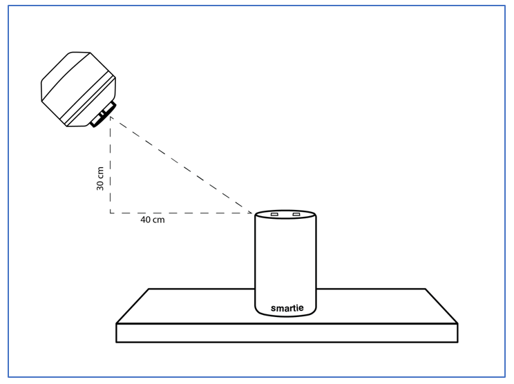
In Figure 1, the mouth simulator is 30 centimeters above the top of the smart speaker rather than the table surface. This is because a smart speaker’s microphone array is typically located on the top surface of the device, as opposed to speakerphones, which typically have microphone(s) located at the base of the device.
Like any loudspeaker, a mouth simulator does not have a flat frequency response; typical mouth simulators have a deviation from flatness of ±10 dB or more within the frequency range from 100 Hz to 8 kHz (the frequency range of male speech). For a mouth simulator to faithfully reproduce an audio signal such as speech, it must be equalized to have a flat response within this range.
Measurements to equalize (and calibrate) a mouth simulator are typically made with a 1/4-inch measurement microphone at a point called the Mouth Reference Point (MRP), centered on the mouth opening and located 25 millimeters (1 inch) in front of the lip ring. To equalize a mouth simulator, its frequency response is measured, then inverted and applied as an EQ curve (a feature built into the audio analyzer). This results in the mouth simulator having a frequency response magnitude that is flat within a specified tolerance (e.g., ±0.5 dB from 100 Hz to 8 kHz).
The test signal should also be presented at a known level. IEEE 1329 specifies a level of -5 dBPa (89 dBSPL) at the MRP, which corresponds to a normal or nominal level of speech. If a speech signal is used, the level should be set using the “active speech level” – a level metric which ignores the silent periods between speech phrases and sentences. The input path of a smart speaker will likely have nonlinear processing such as automatic gain control (AGC). As such, it might be prudent to repeat the test at a few different levels. For speakerphone loudness ratings, IEEE 1329 specifies tests at levels from 79 to 99 dBSPL at the MRP in 5 dB steps.
In the analysis phase, the signal acquired by the smart speaker and uploaded to the IVA will be compared to the stimulus signal. This will require that the two signals have the same audio sample rate. For the input path, smart speakers typically use a sample rate of 16 kHz, which enables a bandwidth of just less than 8 kHz. This sample rate is used in “wideband speech” applications such as VOIP and newer versions of the Bluetooth Handsfree profile (HFP). It’s referred to as wideband, because it has twice the bandwidth of ordinary digital telephone lines (just under 4 kHz), which enables clearer, more natural sounding speech.
If the test stimulus does not already exist, it makes sense to create it at the same sample rate (typically 16 kHz) as the DUT output. Audio analyzers can usually create a stimulus signal at a variety of sample rates. If the stimulus signal already exists, but is at a different sample rate, at some point it will need to be converted to the sample rate of the DUT output. This is easily accomplished with an audio waveform editing software package like Audacity [2] (open source) or GoldWave [3].