Equalization
Equalization (EQ) is the term used to denote an intentional change in relative amplitudes at different frequencies.
Because the analog recording process isn’t linear, equalization is needed to achieve a flat frequency-response curve when using magnetic tape.
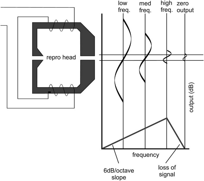
The 6-dB-per-octave boost that’s inherent in the playback head’s response curve requires that a complementary equalization cut of 6 dB per octave be applied within the playback circuit (Figure 3).
Bias Current
In addition to the nonlinear changes that occur in playback level relative to frequency, another discrepancy in the recording process exists between the amount of magnetic energy that’s applied to the record head and the amount of magnetism that’s retained by the tape after the initial recording field has been removed.
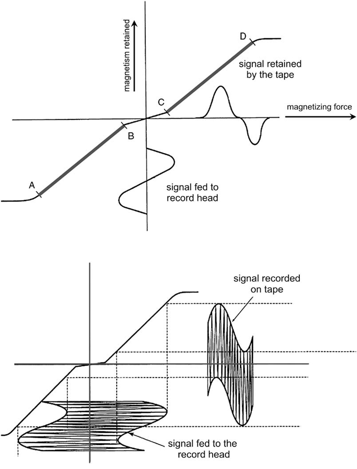
As Figure 4a shows, the magnetization curve of tape is linear between points A and B, as well as between points C and D.
Signals greater than A and D have reached the saturation level and are subject to clipping distortion. Signals falling within the B to C range are too low in flux level to adequately magnetize the domains during the recording process.

For this reason, it’s important that low-level signals be boosted so that they’re pushed into the linear range. This boost is applied by mixing an AC bias current (Figure 4b) with the audio signal.
This bias current is applied by mixing the incoming audio signal with an ultrasonic sine-wave signal (often between 75 and 150 kHz).
The combined signals are amplitude modulated in such a way that the overall magnetic flux levels are given an extra “oomph,” which effectively boosts the signal above the nonlinear zero-crossover range and into the linear portion of the curve.
In fact, if this bias signal weren’t added, distortion levels would be so high as to render the recording process useless.

Monitoring Modes
The output signal of a professional ATR channel can be switched between three working modes:
—Input
—Reproduce
—Sync
In the input (source) mode, the signal at the selected channel output is derived from its input signal.
Thus, with the ATR transport in any mode (including stop), it’s possible to meter and monitor a signal that’s present at a channel’s selected input. In the reproduce mode, the output and metering signal is derived from the playback head.
This mode can be useful in two ways: It allows previously recorded tapes to be played back, and it enables the monitoring of mate- rial off of the tape while in the record mode. The latter provides an immediate quality check of the ATR’s entire record and reproduce process.
The sync mode is a required feature in analog multitrack ATRs because of the need to record new material on one or more tracks while simultaneously monitoring tracks that have been previously recorded (during a process called overdubbing).
