Here’s a quick “checkup” tuning on a basic flown left-right point source rig in a small black box theater. I was on the site working on the comms system and we decided to quickly measure the PA before I left.
This entire process took 10 minutes from top to bottom. The idea here is to move quickly, not getting caught up in the details, and prioritizing the large-scale issues. We’re going to check the aim, make sure both sides match tonally, and also make sure both sides match in level.
The seating area is narrow enough and far enough from the mains that some semblance of stereo is possible. For this, we depart from the usual half-and-half segmentation approach for mains aim and instead try to cover the entire seating area with each side.
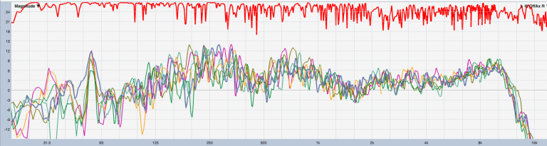
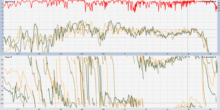
We start with an ONAX (on-axis) measurement, with the microphone placed smack dab in the center of the seating area, which is where both boxes are aimed (Figure 1). There’s a lot of ripple in the high-frequency magnitude response, big dips in coherence, and a confused phase trace. These are all telltale signs of a mistake: we’re measuring with both sides on.
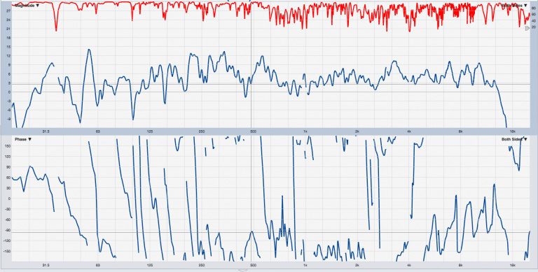
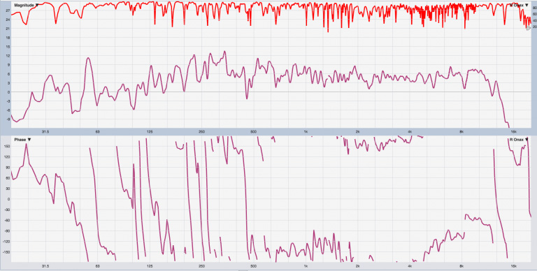
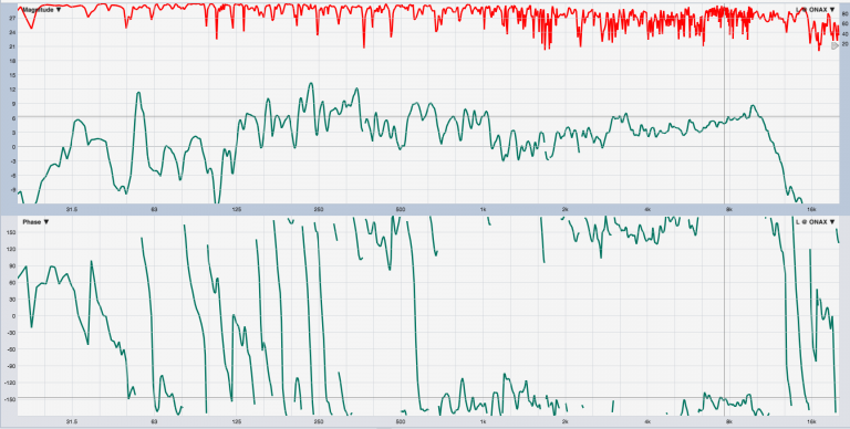
Let’s try again with just the right side (Figure 2). That looks better, but there’s still a red flag in the phase trace – it’s hanging around 180 degrees above 800 Hz. That’s a polarity inversion. This is why it’s important to pre-verify a rig before measuring stuff – that could be a miswired XLR cable in the measurement rig, not a problem with the system at all. Hold that thought – for now, we note it and move on.
Horizontal Aim
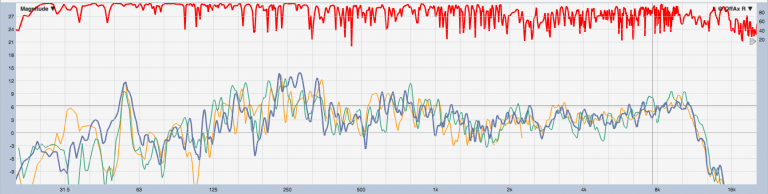
We verify horizontal aim by measuring the response at the outer edges of the midpoint of the seating area. If one edge has more HF roll-off than the other, the aim is off center. If HF roll-off exceeds 6 dB at either edge, we need a wider box. With a helper to move the mic, this takes only a few seconds (Figure 3).
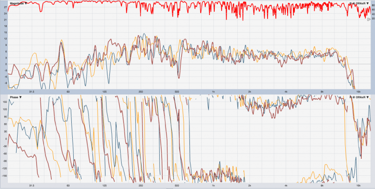
The edges of the seating area have HF that hangs within 2 dB of our ONAX reference (gold trace). These are wide boxes. Horizontal aim is fine.
Vertical Aim
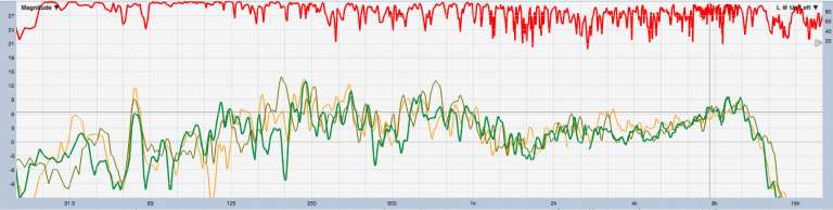
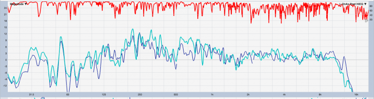
The vertical aim is checked in a similar way, comparing the HF roll-off between the front and back edges and the center ONAX gold reference (Figure 4). Again, the edge responses are well balanced to each other at HF and within 6 dB of gold so the loudspeaker aim is sufficient to cover the seating area as evenly as we can.
Symmetric Check
The left side is put through the same paces. Polarity inversion is still there (Figure 5), with the left side horizontal aim check shown in Figure 6, and then the left side vertical aim check depicted in Figure 7. Truth be told, these are wide boxes and so there’s a large margin of error with the aiming.
Finishing Touches
After running all the test cables and console together in a loop-back, the polarity inversion was revealed to be in the amplifier/loudspeaker part of the system, so I flipped the polarity on both sides in the DSP.
This probably isn’t the “mistake” that it first appeared to be. Likely, the internal passive crossover design inside these boxes requires a polarity inversion of the HF driver for proper summation (common with crossovers using 2nd order filters on both HF and LF, resulting in a 180-degree phase offset at Fc). In other words, it’s a feature, not a bug. This is the type of thing that’s easy to overlook when moving quickly.
Since there’s no subwoofer in the space, and there’s no good way to get a clean LF response measurement, it’s a take-your-pick scenario here. I’d rather have the HF be in absolute polarity with the rest of the system because the LF is going to be quite volatile in such a small room anyway. At any rate, the far more important thing is that all the boxes have matched polarity.
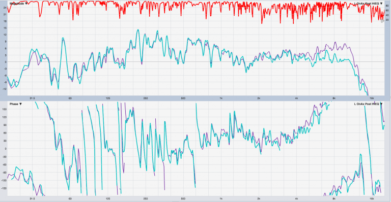
Next I fixed the HF runup around 9 kHz on the left channel with a bell filter (note flipped polarity on phase trace), and this is shown in Figure 8 (Note: purple = pre-EQ, blue = post-EQ). In a direct comparison, it seems that the HF driver of the right main is 2 dB hotter than the left side (Figure 9).
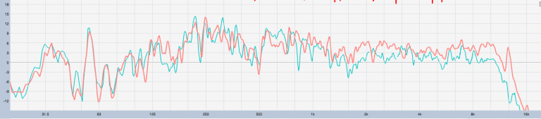
Because I’m more concerned about HF than LF, and we’re dealing with a passive crossover, I just turned the box down rather than try to place a large shelf filter. Yes, now the LF is 2 dB down, but in my opinion that’s far less important for imaging especially given the modal issues in the room (Figure 10).
And we’re done.
If you’re wondering why I didn’t tamp down that devil-horns bump at 630 Hz, note that it doesn’t show up consistently over the coverage of that box, so it’s a localized thing and shouldn’t be fixed with EQ. Overlaying traces from that box taken over the space shows a large amount of variation in the 600 range, and there’s no one-size-fits-all EQ solution here.
Compare that against the HF ramp up at 9 kHz. Since that’s consistent in all locations, it’s a good candidate for EQ (Figure 11).