The First Acousticans
So, who were the early practitioners that discovered equalization?
We have to go all the way back to the Middle Ages when the first pipe organs were being installed in large cathedrals. The pipe organs were put together in workshops, and then taken apart and reassembled in the cathedral.
When the organ was played they found that certain notes “took off,” or blared loudly. These were referred to as “bull” notes (a term still used today).
So the pipe organ maker, by ear, would tune that pipe down in level so it would not excite or cause the room to resonate. This was a long painstaking task, since every pitch had to be perfect.
Plus the ornate structures and curves of the ancient churches did a lot to help diffuse acoustic reflections, and intentionally or not, made pleasing acoustic mediums for the organ music. So the art of sound equalization goes back a long way.
Today we have many tools at hand. I will not go into real time analyzers – TEF, Smaart, etc. – since a discussion of these devices would require their own article. Instead, we will talk about filters.
Third-octave and parametric equalizers all use filters, the difference is their shape and characteristics. We found out earlier that feedback and ring modes are extremely narrow, so we just want to rid ourselves of them without affecting the overall sound system.
The most frequently seen EQ is the 1/3-octave equalizer. Prices can range from $200 to $2,000. It is interesting to note that a very famous “loudspeaker” manufacturer teaches its sales force to always use the best quality equalizer available, and if you have to cut costs at all in the sound system the last thing you cut is the quality of the equalizer. Bless their hearts

Much goes into the quality of an equalizer. Aside from careful attention to noise and distortion specifications, the first thing the designer needs to choose is the filter’s shape or architecture.
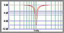
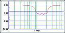
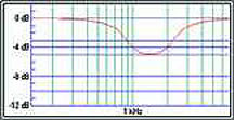
The two most common today are referred to as constant-Q and variable-Q. The Q in equalization deals with the width of the filter as it is raised and lowered. (See Figures 1 & 2).
Notice the constant-Q maintains the overall width of the filter as it is adjusted, whereas the variable-Q varies its width as it is adjusted from wide at +/-3 dB to narrow at +/-9 dB. These architectures or “transfer functions” were developed in the 1930’s. Companies that use them will make their own minor modifications to how they work, but generally speaking this is how they perform.
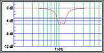
Constant-Q was espoused at a time when analog parametric equalizers were very noisy (most still are), to get rid of feedback without taking music out of adjacent frequencies. The fallacy of this claim is that feedback rarely occurs on ISO (Industry Standards Organization) centers. These are the common frequencies everyone has agreed to use for uniformity on equalizers. (See Figures 3 & 4)
Look at the transfer function of two adjacent frequencies of constant-Q and variable-Q equalizers, and see the gap between the two frequencies on the constant-Q, whereas the variable-Q sums as one. What if the feedback mode was between those two frequencies?
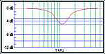
Most professional fixed-installation installers now use 1/3-octave equalizers more for tonal balance, not feedback control. They may move three or four adjacent frequencies up or down a few dB for tone control. (See Figures 5 & 6)
Look at the ripple effect with constant-Q. It looks like the intelligibility distortion known as “comb-filtering.” Now look at the variable-Q example and see how the frequencies sum more smoothly. Which do you think sounds better?
Constant-Q is marketed strongly through the “lower-end” of the rock ‘n roll market. One engineer from a well-known audio company has privately said their older equalizers sounded much better than their new constant-Q equalizers but they changed because of marketing pressure.
Another difference is what is known as designing a “band-pass” type equalizer. In this type of equalizer (which requires extremely high-quality componentry) all the EQ filters are always in the circuit regardless of the position of the faders. This guarantees that the overall noise level will not change much as the filters (or sliders) are moved up or down.