

This article is provided by Rane as part of the Rane Library and originally appeared in the Syn-Aud-Con Newsletter, vol. 31, nos. 2 & 3, 2003
In his landmark 1994 AES paper, Neil Muncy described a common equipment design error that allows current flowing on the shields of audio wiring to enter equipment and cause audible interference.
He called this design error “the Pin 1 problem,” because it was an improper connection of the shield terminal, pin 1 in XLR connectors.
The Pin 1 Problem
Cable shields are essentially an extension of the shielding enclosure of equipment, and they should be connected directly to that shielding enclosure.
To make equipment cheaper to build, manufacturers started connecting cable shields to the circuit board’s common trace, then took that trace to the chassis. The problem is that any voltage drop across the wiring that is common to both the shield current and the circuit’s path to ground will be injected into the audio circuitry.
Shield currents include the noise currents coupled into ground by power line filters, potential differences between “ground” at opposing ends of long cable runs, and the shield acting as an antenna, picking up RF dimmer noise and other radio signals. It’s quite common to have AM, FM, and TV broadcast signals flowing on the shields of audio wiring.
Neil has observed that most RF interference to audio equipment is caused by a pin problem, and some recent research I’ve done has convinced me that he’s right.
Microphone Examples
Here’s the inside of a rather expensive condenser mic (Figure 1), the manufacturer of which has long insisted that the shields of mic cables must be connected to the shell in order to prevent RF interference. A quick look at the photo tells us why—this mic has a screaming pin 1 problem at VHF frequencies!
A good connection in the audio band can be a bad connection in the RF band

The black wire takes pin 1 to the body of the mic, and the orange wire takes pin 1 up to the circuit board. At audio frequencies, that works just fine. But at 56 MHz (the frequency of TV channel 2), the inductive reactance of the black wire is about 4Ω. If you try to use this mic in downtown Chicago with a properly wired mic cable, the shield current induced by Channel 2, Channel 5, and a bunch of FM broadcast stations causes enough voltage drop in the black wire (which the orange wire adds to the audio circuitry) that both the video and FM signals are clearly heard! Rick Chinn’s review of this mic several years ago for a magazine noted RF interference from TV stations, the closest of which were 13 miles away!
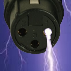
This mic has a pin 1 problem too (Figure 2), although not as severe—it takes about 6 dB more RF to cause audible interference. Here, the shield goes to the chassis through the tiny wire connecting pin 1 to the broad tab holding the connector’s retaining screw. The combined length of that path is on the order of 1 cm, which results in about 2Ω of inductive reactance at 60 MHz. Again, circuit common is connected to pin 1 and sees the drop across the inductance. I was first alerted to the problem in this mic when I noticed that tightening the screw reduced the interference by about 3 dB!

The pin 1 problem works in reverse too—any RF noise currents (digital clock noise, for example) flowing in that common impedance create a voltage drop that is coupled out to the shield. The shield, acts as an antenna and noise is radiated to nearby equipment and wiring. It’s not at all uncommon to see shield paths inside equipment 3-5 inches long! At 100 MHz, a 5” long wire is about 60 Ω! At 1 GHz, it’s about 600 Ω.
Line Level Example
Figure 3 shows the rear panel connections to a DSP unit that has a bit of a noise problem. Looking behind the panel, we see the circuit traces go to the chassis via the two black screws at approximately the 4” and 7” points on the ruler that has been laid on top to show dimensions. All the incoming shields are bused together and go to the screws. These long leads (typically 2-4” with all the zigs and zags) are like open doors to radio frequency signals—any current flowing on the shields radiates inside through antenna action, and noise inside the box is coupled out onto the shields, which also act as antennas.

Internal conductors (including PCB traces) that connect to pin 1 can act as antennas.
The Right Way
There are better ways to do this. Some manufacturers (Figure 4 shows a Rane product) provide a chassis screw next to pluggable strip connectors for proper termination of the shield. Inside, the signal leads go directly to RF filter networks.
In a series of tests I recently did on more than 45 condenser mics using standard XLR connectors, nearly all experienced serious interference from cell phones, and about one-third experienced significant interference from TV broadcast stations and/or my ham talkie.


