A properly gathered balloon will reveal the anechoic response of the loudspeaker at all listener angles.
Since the direct field of a loudspeaker is considered to be largely independent of the acoustic environment (at least at short wavelengths), direct field equalization based on balloon data has a strong theoretical basis.
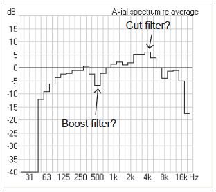
Figure 1 shows the axial frequency response of a multi-way loudspeaker. The dip in response at 500 Hz is due to phase cancellation between multiple drivers in the box. A boost filter at this frequency center will restore the axial response to flat.
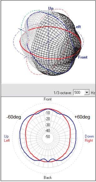
But observation of the entire radiation balloon at 500 Hz (Figure 2) shows that the devices come into phase at two off-axis positions, possibly producing a significant peak in the response for many of the audience members.
The “correction” made to the on-axis response will produce an even less ideal response off-axis where a greater number of listeners are located, or even worse at a microphone position causing a feedback problem.
Devices that have a destructive phase offset at one listener position are likely to have an in-phase relationship at another. The notch might better be addressed by the use of precision signal delay between the elements.
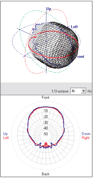
In general, for a single transducer equalization will inflate or deflate the balloon at a specified octave band. The same effect occurs at all angles around the device.
But what is often needed is a re-shaping of the balloon, which can be accomplished by using multiple elements and varying their physical spacing and relative delay.
This is the heart and soul of beam-steered loudspeakers. Boost and dip filters applied based on the axial response only can change the directivity of a multi-element device, since the phase shift introduced by the filter can cause a change in the way that the multiple elements interact.
It should be noted that psychoacoustics also plays a role in this.
Peaks in a frequency response are much more audible (and bothersome) to humans than dips in the response. We are more aware of “too much” than “too little.”
A safe approach to equalization that embodies the theories described herein is to avoid the use of boost filters when calibrating a sound system, since it is better to have “too little” than to have “too much.”
If a sound practitioner used the axial response for equalization, and cut-only filters to smooth the resonant peaks, acceptable results would likely be attained for most listeners since off-axis lobes will not be “inflated” by the process.
Conclusion
Loudspeaker balloon data is useful for direct field equalization of a loudspeaker. It is plausible that the complete equalization of the direct field can be determined from the axial frequency response and the spherical balloons.
The remaining equalization chores can be left to the installer or commissioner of the system. This can include compensation for boundary loading, device coupling, etc.
The possibility also exists based on the above for a manufacturer to provide an appropriate equalization curve in the form of a simple magnitude vs. frequency plot or as a setting that can be imported into popular digital signal processors.