
A couple of years ago marked the 40th anniversary of Altec Lansing’s passive third-octave “continuous” equalizer that began modern sound system equalization.
It didn’t start as a graphic equalizer, but rather, was three rows of eight knobs on third octave centers. A companion third-octave real-time analyzer, three rows of eight VU meters, provided a means to measure a sound system.
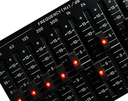
Subsequent Altec EQs replaced the knobs with a row of sliders, earning the name “graphic” because their positions provide a graphic display of the equalizer’s response.
Today the favored device to quickly equalize temporary sound systems is still a graphic equalizer, whose third-octave filters on standardized frequencies give engineers a consistent set of EQ controls, as well as providing a universal vocabulary for describing a wide range of audio tones.
I won’t argue that there aren’t better ways of equalizing and optimizing the response of a sound system, but when time is tight, a good graphic EQ in the hands of a good engineer is usually “good enough.”
A quarter-century ago, Crown’s Techron division unveiled the TEF System 10, the first portable Time Delay Spectrometry acoustical measurement system. Now owned by Gold Line, TEF provides near anechoic measurements due to its tracking filter.
Two decades ago, Meyer Sound developed source independent Fast-Fourier Transform measurement using Hewlett-Packard’s 3582A dual-channel FFT analyzer, released as SIM II in 1992 and updated in 2003 as SIM 3.
SIA Software (now Rational Acoustics) Smaart put FFT onto laptop computers one decade ago, providing high-definition measurement to the average sound engineer.
More recently, the new Studio Six Digital FFT iPhone application puts single-channel FFT measurement into the hands of the masses.
With higher resolution, it becomes obvious that some frequency response problems aren’t fixable with the average equalizer, whether graphic or parametric.
Since being introduced in the 1970s, third octave graphic equalizers have been a standard in live sound, offering a set of overlapping filters that cover all frequencies. Professional sound systems employ one for each channel: two for stereo main systems and one for each channel of floor monitors.
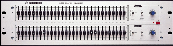
The original Klark Teknik DN 30/30, long ago replaced by the nearly identical DN360, has 30 combining third-octave filters, called such because of the overlap of a filter into the next filter’s control.
Described as variable bandwidth, these filters provide broader response at low boost or cut, which narrows with higher gain. This model has been updated with the DN370, which adds a couple of parametric notch filters and a variable high-pass.
Early on, engineers who understood the difference in filter types sometimes requested the vintage Klark Teknik DN27 instead, preferring its sharper filters over those of the DN360. KT’s programmable DN3600 provided a choice of either filter type.
Currently the KT Helix DN9340 provides five graphic filter types, in addition to dual dynamic EQ filters, four notch filters, a dozen parametric filters per channel, and the companion moving fader Rapide remote, which also can control the graphic EQ on Midas’ XL8 and PRO6 consoles.
Not only are a graphic filters spaced at third octave intervals, they’re generally a third of an octave wide, meaning the 3 dB down points are at the next filter’s center frequency. This means the combined response of two filters on either side of an unused filter’s frequency combine to work on that frequency as well.
An old rule of thumb with graphic EQs is that if you’ve used more than half of their sliders, you have “over equalized” and it’s considered good practice when this happens to simply flatten out the graphic EQ and start over with a flattened equalizer.


