How does this configuration work?
As mentioned above, our goal is to achieve cancellation at the back.
Therefore we first need to match the phase for the two subwoofers at the back and then we’ll invert the polarity on the back subwoofer.
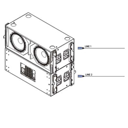
The wave coming out of the front subwoofer in Figure 11 reaches the front baffle of the back subwoofer with a delay that is a function of the distance between them. This distance is a quarter wavelength at the reference frequency, i.e. λref / 4.

How long does it take for the wave of the front subwoofer to reach the back subwoofer?
We know that:
c = e / t, where
c, is the speed of sound (344 m/s) e, is distance
t, is time.
From there, t = e / c
Let’s call tfb the time it takes for the wave of the front subwoofer to reach the front baffle of the back subwoofer. We now solve for t to calculate tfb,
tfb = e / c = (λref / 4) / 344
If we now use a signal processor to add this delay time to the back subwoofer, both subwoofers will be in phase at the back.

One could say that we are applying electronic delay to the back subwoofer so that it “waits” for the arrival of the wave of the front subwoofer, which gets there late due to the distance between both subwoofers. Inverting the polarity on the back subwoofer will produce cancellation.
Anechoic chamber measurements
Polar plots and isobar maps illustrate the effectiveness of this cardioid configuration.

It can clearly be seen that a cardioid, heart shaped, pattern is radiated, as desired. The pattern changes slightly with frequency. 160 Hz is the lowest frequency shown, as it corresponds to the anechoic chamber’s frequency limit.
Keep in mind that you should divide the frequencies shown by 4.5 to calculate the equivalent frequencies for an 18” subwoofer, so that 160 Hz in our scaled down exercise would correspond to 35.5 Hz.

Isobar maps represent a system’s coverage in degrees (vertical axis) as a function of frequency (horizontal axis). The color scale on the right-hand side shows that white color (or the limit with blue) corresponds to -6dB with respect to the centre.
It can be seen that we have roughly -6dB at +90º and -90º throughout the band, i.e. a coverage of 180º.
Stay tuned for the coming articles in this series, where we’re lay out some more examples. Want to get a jump on the reading? Head on over to the DAS Audio Website where you can DAS Audio Engineering Department.