Set-up for scaled down measurements
For the scaled down measurement in this example DAS Arco 4 loudspeakers cabinets have been used to simulate the subwoofers.
The spacing has been chosen to correspond to 1/4th of the wavelength of the subwoofer upper crossover frequency.
Again, subwoofer cut-off frequencies are:
HPF LR24dB/Oct, 30Hz x 4.5 = 135Hz
LPF LR24dB/Oct, 85Hz x 4.5 = 382Hz
And the wavelength for the upper crossover frequency is:
λ = c/f = 344/382 = 0,9m
1/4th of the wavelength is λ/4 = 0,9/4 = 0.22m = 22cm
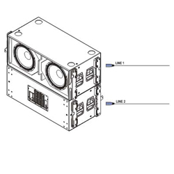
Figure 2 shows cabinet placement for this example. Cabinet front baffles are spaced 22cm, and, in this case, the distance from the back cabinet to the measurement microphone was 90cm.

Once we have worked out what the cabinet spacing needs to be for this specific configuration, we can start with the procedure, which is shared by the rest of cardioid configurations shown in this article.
Procedure
The procedure is as follows:
1) Place the microphone behind the enclosures, at the spot where you want the cancellation to take place.
2) Start with just the front subwoofer band. We’ll use the “Delay Finder” utility to add the required delay on SATLive to the channel carrying the reference signal.
3) Measure the magnitude frequency response for the front enclosure before doing phase adjustments. This way we’ll be able to compare the initial situation with the cardioid configuration.

The measurement can be seen in Figure 3. The subwoofer’s phase trace will always be shaped like an upper case U letter, or a smile.
4) Mute the front subwoofer band and unmute the back subwoofer band.
5) Do not use the “Delay Finder” again!!! (i.e., do not synchronize the reference signal to the measured signal again). Remember that we are comparing phase on both subwoofers, i.e. we are measuring the difference in time arrival between the two signals as a function of frequency.
Therefore the synchronization delay for the reference signal should not be changed on the measurement software again.

6) Measure the back subwoofer band and compare the phase and amplitude curves with those of the front subwoofer. The result can be seen in Figure 4.
7) If necessary, adjust the gain of the back subwoofer so as to match the level of the front subwoofer at the measurement position. If needed, you could always apply filtering (HPF, LPF or EQ) to match the levels in the whole of the subwoofer passband.
8) Add delay to the back subwoofer until its phase trace overlaps with that of the front subwoofer. Do not forget to save the curves.